|
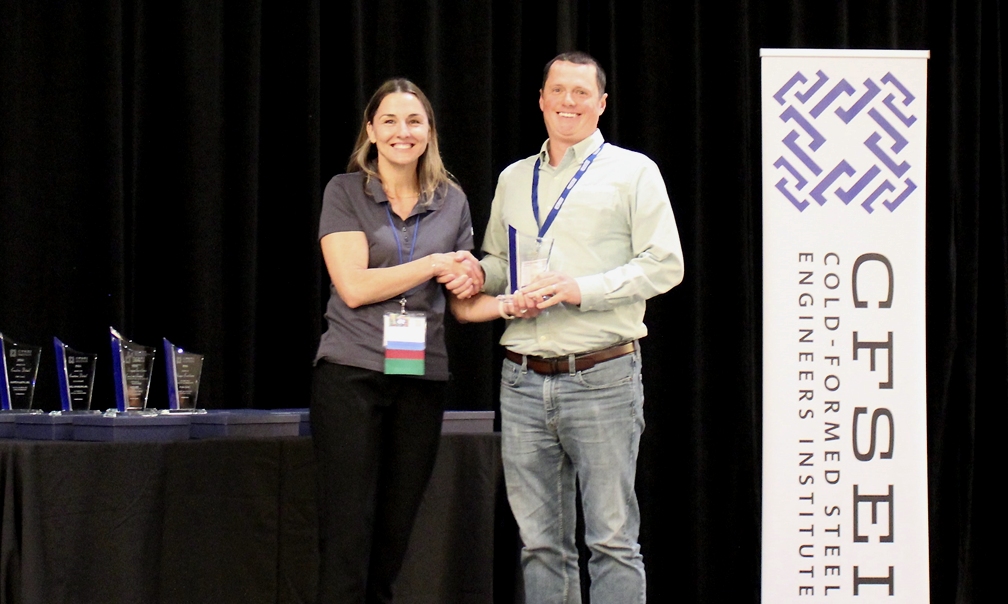
2026 CFSEI DESIGN EXCELLENCE AWARD WINNER
THIRD PLACE - RESIDENTIAL/HOSPITALITY
MARTIN/MARTIN, INC.
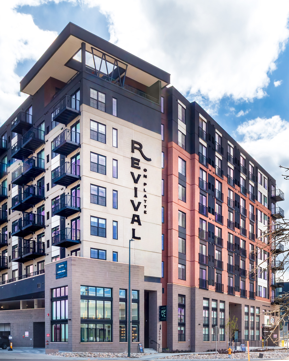
REVIVAL ON THE PLATTE
DENVER, COLORADO
 Revival on the Platte Revival on the Platte
2506 West Colfax
Denver, CO 80205
Completion Date: April 2025
Owner: Mortenson Development
Architect of Record: Kephart and Base4
Engineer of Record for Structural Work: Fortis Structural LLC & Martin/Martin Inc
Cold-Formed Steel Specialty Engineer: Shane Ewing, Martin/Martin Inc.
Cold-Formed Steel Specialty Contractor: Anthony Herrmann, BLUvera
Award Entry Submitted by: Grant Doherty, Martin/Martin, Inc.
Project Background
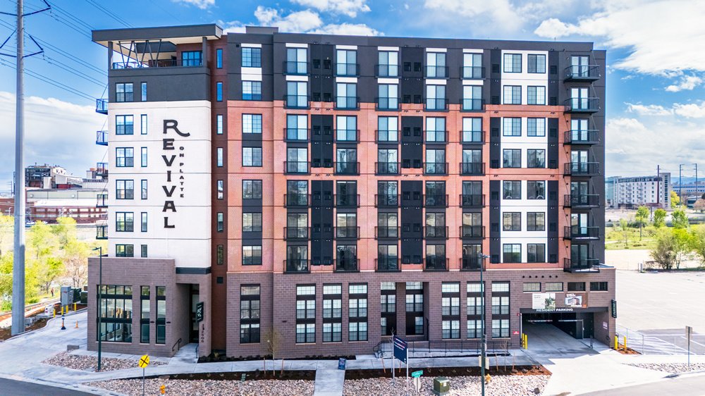
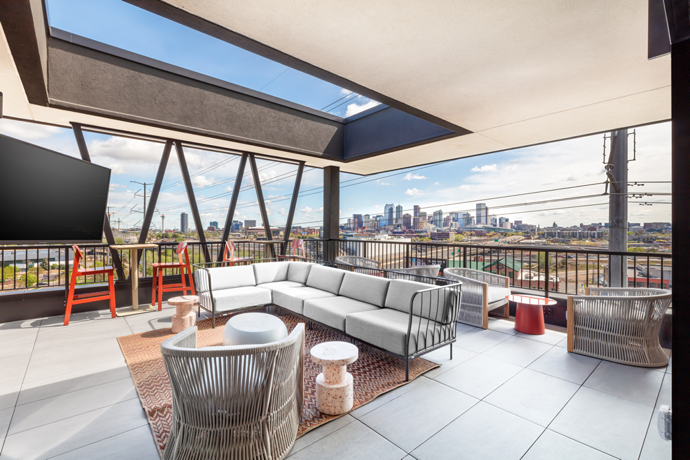
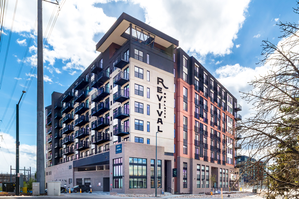
The Revival on the Platte is a seven-story, load-bearing cold-formed steel (CFS) residential structure over two levels of concrete podium. It sits in the heart of Denver, across from Empower Field at Mile High. The project has mass transit access, sits adjacent to bike paths and is within walking distance of Denver’s sports venues.
Mortenson Development led the project and delivered it through a design-build approach. Mortenson Construction, BLUvera LLC, Kephart, BASE4, Fortis Structural LLC and Martin/Martin Inc. collaborated on the design and construction.
Martin/Martin served as the specialty engineer of record for all CFS systems. The firm performed the lateral analysis and designed the lateral load-resisting systems for the seven-story structure above the podium. The team also provided all LOD 400 modeling and fabrication detailing for prefabricated CFS framing.
Design Challenges and Solutions
The team chose a fully CFS-framed load-bearing and lateral load-resisting system to maximize the capabilities of BLUvera, Mortenson Construction’s CFS roll-form fabricator and prefabrication arm. BLUvera’s multi-profile roll-form machine could fabricate heavy 6-inch wall profiles and joist profiles up to 12 inches deep. That allowed Martin/Martin to develop an efficient CFS design.
To eliminate or minimize field-installed structural steel and concrete, the team chose a strap-bracing system to resist lateral forces. They also selected simple cementitious deck panels to reduce costs and minimize building mass.
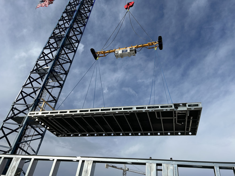
The capabilities of the client’s roll-form equipment also allowed the team to maximize prefabrication. Typical floor and roof framing used 10-inch joists prebuilt into cassettes. The factory in St. Paul, Minnesota, installed decking and MEP systems in the cassettes.
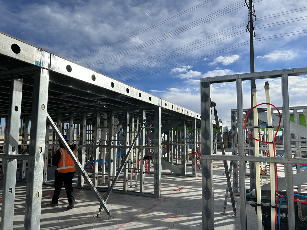 Similarly, the team panelized all structural walls, pre-installed strap bracing and MEP systems and fully finished the exterior wall panels. The team incorporated principles of Design for Manufacture and Assembly (DfMA) to ensure efficient factory use and deliver a cost-effective, high-quality product. Similarly, the team panelized all structural walls, pre-installed strap bracing and MEP systems and fully finished the exterior wall panels. The team incorporated principles of Design for Manufacture and Assembly (DfMA) to ensure efficient factory use and deliver a cost-effective, high-quality product.
This level of prefabrication required extensive coordination. Mortenson, BLUvera, Martin/Martin and BASE4 held weekly BIM coordination meetings to review MEPFP routing in relation to framing. That process resulted in unique web punch-outs in floor joists and frequent adjustments to the framing to accommodate those systems.
In addition to the extensive effort to coordinate, model and create fabrication drawings for complex prefabricated floor and wall elements, the following sections highlight several of the project’s design challenges and solutions.
Stair Shaft Girts
The building’s two stair shafts were both located at the exterior. Because the lateral system used cold-formed steel, the design did not include a traditional core wall system around the stairs. As a result, the team had to run the wall eight levels tall — seven occupied levels plus the roof overrun — without the intermediate support typically provided at each floor.
To achieve this design, the team used built-up CFS girts at each level. These girts carried the full lateral wall load at each level and dispersed out-of-plane loads into the stair shaft end walls. Along the long direction of the stair, the girts typically consisted of four 600S250-118 members and two 600T300-118 members. This configuration spanned the 23-foot stair opening while remaining within the typical 6-inch wall depth of the structure.
Exterior Elevator Shaft
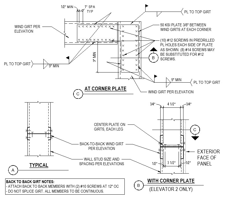
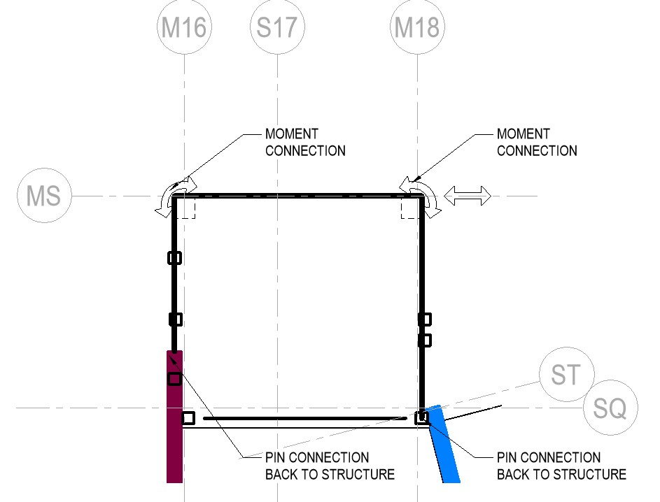
One of the elevator shafts extended beyond the typical exterior face of the structure on three of its four sides. Without a traditional concrete core system, the team had to design this three-sided box to remain nearly self-supporting over the full height of the building.
To achieve this design, the team engineered the three-sided box to act essentially as a horizontal moment frame. Structural steel plates at the two exterior corners connected the cold-formed steel panels and engaged all three sides as a full moment frame system. This approach also allowed the exterior walls to be fully finished.
Rated Shafts
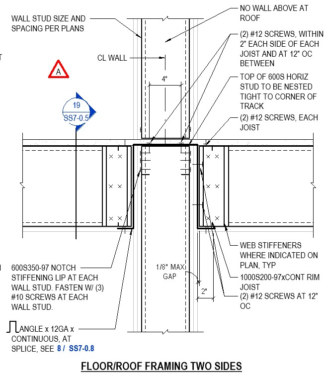
Denver’s requirements for rated shaft wall assemblies required Martin/Martin to develop a unique system. The design had to maintain a continuous rating, as required by the AHJ, while supporting the floor system and load-bearing walls.
To achieve this, the team allowed sheathing to run continuously along both sides of the walls. They designed light-gage Z plates to hang from the top of the wall. These plates were sandwiched between the panels that supported the floor cassette framing.
The team installed the sheathing layers at the top of the panel in the fabrication shop. They also installed the Z plates in the shop to maximize shop labor and reduce field labor.
|