
FAQ OF THE MONTHJUNE 2026
ASTM A1003 Table 3 (Mechanical Properties, Base Metal) lists minimum mechanical properties requirements for the various steel grades. However, Table 3 does not list minimum requirements for the tensile strength of NS grade steels. The tensile strength is needed to calculate screw capacities per AISI S100 Chapter J. Thus, the SFIA catalog conservatively provides allowable shear and tension capacities based on the minimum required yield strength for NS grade steel. MAY 2026
APRIL 2026
Also, should I design the wall stud for a minor axis bending resulting from ¾” alignment?
The Section B1.2.3.2 alignment provision is a connection design consideration and is not intended to be a building construction alignment limitation. The intent of this section is to provide guidance to maintain an assumed axial load path connecting the upper and lower stud framing. In-line framing assumes the load path flows from the upper stud through the floor interface to the lower stud or foundation. The alignment provisions are based on extensive testing that illustrated the ability of the floor joist, track and bearing stiffener assembly to achieve the assemblies web crippling capacity. Thus, concentric loading of the stud is maintained, and a minor axis bending need not be considered. MARCH 2026
 FEBRUARY 2026
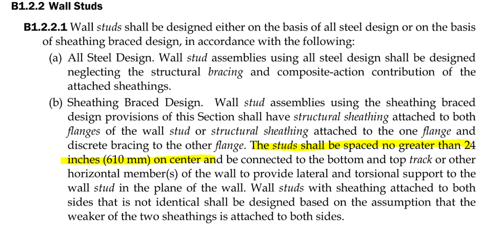
For structural wall studs the AISI S240-20 North American Standard for Cold-Formed Steel Structural Framing Section B1.2.2.1 provides detailed information for all-steel design and sheathing braced design. An all-steel design is the preferred method of bracing for structural wall studs. Section B1.2.2 provides additional information and user notes on different bracing conditions for wall studs. For nonstructural studs, it is usually fine using full height sheathing braced design. When sheathing doesn’t go full-height, then discreet steel bracing (flat strapping and blocking or cold-rolled channel (CRC) with clips) may be used on the portion of the wall that is not fully sheathed on both sides. JANUARY 2026
B5.2.2.2.3.4 Gypsum Board Panel Sheathing Section B5.2.2.3.4 requires a 0.35 reduction factor be applied to all unblocked gypsum board shear wall assemblies (i.e. shear walls with no panel blocking). The panel blocking may be screw attached minimum 33-mil flat steel straps. The blocking provides a load path between adjacent panels. The blocking functions similar for the diaphragms listed in Table B5.4.2.2-1 of this Standard and the SDI-AISI S310 side lap connection in profiled metal deck diaphragms. These standards enable one to design a diaphragm without consideration of side lap connections, but the diaphragm capacity is reduced. This is essentially what the 0.35 factor is doing for unblocked gypsum board shear walls. The 0.35 factor is based on the tested performance of gypsum board shear wall assemblies. DECEMBER 2025
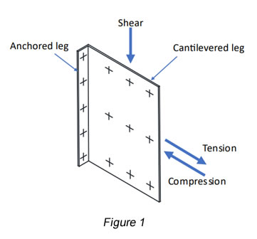
The flange bending, however, requires engineering judgment. The bending of the flange theoretically may be evaluated using yield line theory. In the absence of a rigorous yield line evaluation, a design method based on the cantilever beam analogy may be employed. Method No. 1 This method has been used in the metal building industry for hanging loads off of a purlin flange. The allowable load determined by using the cantilever beam analogy (Figure 1) assumes elastic behavior as follows: Mn = SxFy = (bt2 /6) Fy where e = distance from load application to the web centerline, b = 2e, Fy = yield stress, t = base steel thickness and Ω = 2.0 (AISI S100 Section A1.2). However, one could assume the development of the plastic moment, thus using the plastic section modulus in lieu of the elastic modulus. Therefore, when using the plastic section modulus Sx = bt2/4. 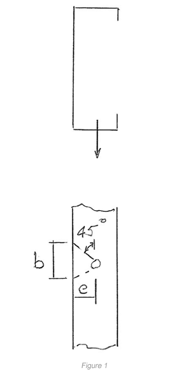 Method No. 2 The provisions of AISI S240 Section B3.2.5.2.2, Deflection Track Connection for C-Section Studs, are based on a cantilever beam analogy. Thus, one may consider the use of Eq. B3.2.5.2.-1 to determine the load capacity of the flange. 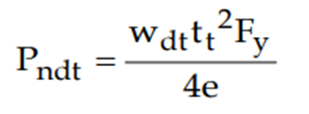 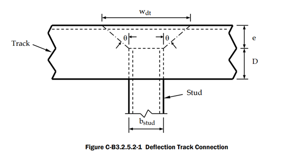
NOVEMBER 2025
OCTOBER 2025
What is the recommended on-center spacing of screws and what is number of screws for composite action (interaction) between the individual members of a stud pack?
Based on extensive research, SDI-AISI-S100-2024, North American Specification for the Design of Cold-Formed Steel Structural Members Section I1.2 provides both prescriptive requirements and rational analysis for compression members composed of multiple cold-formed steel members. These design provisions are not limited to only two sections in contact in the stud pack. The requirements of both editions of AISI S100 incorporate the on-center spacing of the intermediate fasteners and the required strength of the fastener connections. Note, these provisions apply only to the axis of buckling that requires shear force transfer between the individual sections.
SEPTEMBER 2025
Welding is permitted and it has been used to attach the bridging members directly to the stud web. However, for a 10” deep section, which will experience significant twisting under load, the omission of the clip is not recommended. Considering the synergism of the assembly components, if sheathing is present in combination with the CRC a 10” stud should be adequately stabilized. AUGUST 2025
There are conditions where we have 2-hour and 3-hour fire rated stud walls where the wall has (2) or (3) layers of sheathing on each face. For tall walls, the weight of these layers can be way more than 100 lb/ft. Based on the standard language above, should this weight be Considered or Not Considered when evaluating the nominal axial load acting on the stud wall?
Engineers generally interpret the Standard to mean that the weight of the sheathing should not be considered superimposed load. "Sheathing materials" may be thought of as including all non-ancillary or non-decorative layers. Since two and even three layers (of gypsum panel products) are commonly used, and fire tested as such, one would not consider any of the gypsum as part of the "superimposed" load. This Standard requirement applies most often when interior partitions are supporting ceilings or floors from above. This discourages closely spaced nonstructural members used to support mezzanine floors. JULY 2025
Back in the day, the concrete, red iron and wood folks had these types of general limits for ‘practical’ serviceability.
There are no recognized rules of thumb. Engineers typically have tools (e.g. software) and tables at their disposal to calculate joist requirements. However, in the absence of tools we are aware the following have been used for preliminary design estimates:
Even though shallower members could work, the “bounciness” and feel of the floor system could be problematic. Therefore, in addition to the code mandated L/360 for floors, some engineers use L/480 (live load only) for stiffer floors. JUNE 2025
AISI S240-15 has a definition for “repetitive framing” which stipulated a maximum spacing of 24”. Thus, AISI S240-15 limited the use of the standard to assemblies having stud spacing not greater than 24” on center. AISI S240-20 deleted that definition and the 24” limit. Thus, enabling spacing greater than 24” on center were applicable. The sentence you cited was added to Section B1.2.2.1 and other applicable design provisions that are based on testing/research studies where the maximum spacing was limited to 24”. MAY 2025
ASTM C754 does require fastening of corner and jamb studs to top and bottom track, but this was written in a time when building floor-to-floor vertical deflection was less of an issue than it is today. These connections are still required, since ASTM C754 is directly referenced by Section C1 of AISI S220, North American Standard for Cold-Formed Steel Nonstructural Framing. However, the connection may be made using an alternate method to a screw from the track flange to the stud flange. Some alternate methods include a slotted track or a proprietary clip. It should be noted that ASTM C754 stipulates that studs away from corners or jambs do not need to be attached to tracks. Section 5.3.1.3 states “Studs shall engage both the floor and ceiling runners”. The operative word is “engage”. Whereas Section 5.3.2.1 “Studs located adjacent to door and window frames, partition intersections, and corners shall be anchored to runner flanges by screws or crimping at each stud and runner flange”.
APRIL 2025
Traditional limit states associated with the occurrence of prying action are:
Based on the UNT study on screw attached clips two additional strength limit states have been identified and are addressed in AISI D114:
D114 also imposes a deflection limit state.
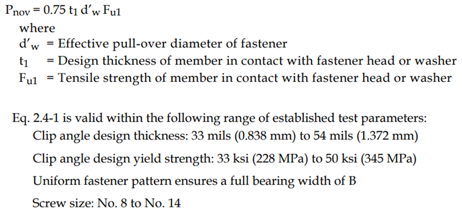
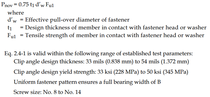
The pull-over strength limit state, Pnov is defined as,
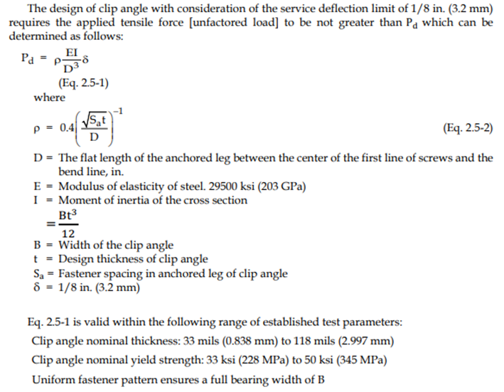
The D114 deflection limit state is as follows:
Thus, because a deflection limit is imposed for thicker clip angles, within the scope of D114 the traditional prying action limit states are not a design consideration. Also, the UNT research determined that prying action is essentially eliminated at the peak load when the clip experiences shape changes. MARCH 2025
FEBRUARY 2025
AISI S240 stipulates a maximum height-to-length ratio, h/w, as defined by Table B5.2.2.3-1. Whereas AISI S400 Table E2.3-1 provides the maximum height-to-length ratio, h/w, for seismic design. When reviewing the respective tables note that footnote 3 provides additional guidance for computing the nominal strength for shear, Vn when h/w is greater than 2:1 but less than 4:1. JANUARY 2025
DECEMBER 2024 QUESTION: 
Why is my limiting height value smaller for Fy = 50 ksi than for Fy = 33 ksi? ANSWER: 
For thin cold-formed steel cross sections local buckling impacts both strength and stiffness. The following figure illustrates local buckling of the compression flange. Local buckling can be thought of as a softening of the cross section. The cross section is no longer working to its full potential.
Using the Effective Width Method of Appendix 1 of AISI S100, the following numerical values illustrate the impact of local buckling for a 6” deep 33 mil profile:
NOVEMBER 2024 QUESTION:
ANSWER:
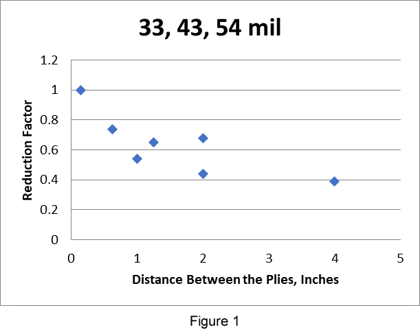
The effective strip method assumed continuous sheathing. If the sheets are lapped, the same reduction factor can reasonably be applied.
QUESTION: Just for my clarity as the verbiage change in S400-20 is not as direct as S400-15. The below verbiage just seems to be removed from each assembly section. Would the following still apply for shear walls and strap braced walls in S400-20? Cold Formed walls w/ Wood Sheathing (from S400-15):
Strap Braced Walls (from S400-15):
Also do you know of any published design examples following the steps of S400-20? ANSWER:
Although, not based on AISI S400-20, AISI D113-19, Cold-Formed Steel Shear Wall Design Guide, illustrates the design procedure for the consideration of expected strength and overstrength. Determination of the overstrength factor, ΩE, is updated in S400-20, but application of the factor is as illustrated in D113-19. Information regarding AISI D113-19 can be found at https://buildsteel.org/technical/codes-and-standards/aisi-releases-cold-formed-steel-shear-wall-design-guide-2019-edition/
QUESTION: AISI S240-20 Section B5.2.1.2 (b) states:"(b) For a Type II shear wall, the nominal strength [resistance] for shear, Vn, is based upon a screw spacing of not less than 4 inches (100mm) on center." Does this imply that 4" is the minimum screw spacing at the sheathing panel edges and the respective capacities are limited to 4" spacing, i.e. 2" and 3" spacings shown in tables B5.2.2.3-1 and B5.2.2.3-2 cannot be used. ANSWER:
QUESTION: AISI S220, North American Standard for Cold-Formed Steel Nonstructural Framing, Section A1.2.1 has the following limitations:
I am struggling with limit No. 2. For example, doesn’t a 100 lb/ft of superimposed axial load, exclusive of sheathing material, negate limitation No. 3?
The key to Section A1.2.1 limitations is that all the limitations must be met for a member to be considered nonstructural. Also, limitations 1 and 2 apply to systems, i.e., members in a wall system, whereas limitation 3 applies to each member only. So, it would be okay to support a piece of equipment that is 300 lbs if the load is distributed over the length of the wall and no individual member was assigned to support more than 200 lbs. Limit 2 applies most often when interior partitions are supporting ceilings or floors from above. This discourages closely spaced nonstructural members used to support mezzanine floors.
QUESTION: Hello - I was curious if you were aware of a typical detail you could point me to as a starting point for typical penetrations through plywood sheathed light frame stud shear walls. I work as a structural engineer, and we are trying to specify the appropriate detailing for new duct penetrations through a new shear wall. The duct penetrations are roughly 30"x30” but vary in size across the building. Any assistance would be greatly appreciated.
There is no document that specifically addresses force transfer around openings for cold-formed steel framing. However, the APA Technical Note T555A “Design of Force Transfer Around Openings (FTAO)” summarizes the design concept and technical issues regarding force transfer around openings. The document is a download from https://www.apawood.org/ftao.
QUESTION: Currently, I am involved in design cold-formed steel framing. Honestly, I am facing the difficulty to locate information to gain an understanding the cold-formed steel framing design. While in school I didn’t study any material related to cold-formed steel design. In the school syllabus, they focused more on concrete structures and hot-rolled steel structures. I am trying to find material for cold-formed steel design, but there is not much to find. Therefore, I emailed you to get more information about cold-formed steel framing. My question is: Could you be please guide me with some recommendations and references (book, class note, online sources, training etc.) on how I can improve my skills on cold-formed steel framing design to build a strong background on the subject?
There are several educational opportunities available.
QUESTION: I am working on a large senior housing project which is required to have 2-hour protection of all structural components: bearing walls, columns and floor-ceiling assemblies. I would like to confirm the requirements for meeting this 2-hour rating (particularly for the walls), preferably in the form of UL listings. The structure is assumed to be bearing walls at corridors and exterior walls. Typical floor-ceiling assembly of upper floors and roof are to be 18" deep trusses. The other specific aspect I would like to confirm, is if there is any height limitation to meeting the 2-hour rating requirement as the ground floor has a 16'-0" floor-to-floor height.
You may find the following two documents helpful:
There are multiple 2-hour assemblies for both load-bearing and non-load bearing cold-formed steel framed walls, and structural floor-ceiling and roof-ceiling assemblies. For these assembles, there are no height limitations other than the structural capacities of the members themselves. So as long as structural analysis shows that the members can span your project’s 16’ height and they meet the UL design requirements, then there is no additional height limitation requirement from the fire rating.
QUESTION: Does AISI D114, Clip Angle Design Guide, require consideration of prying action when evaluating the anchored leg of a clip angle?
Traditional limit states associated with prying action are:
However, based on the University of North Texas study on thin screw attached clips two additional strength limit states were identified and are addressed in AISI D114:
The pull-over strength limit state, Pnov is defined as,
The pull-over strength design equation was calibrated to test results. Thus, any prying effects are included in the design equation. Therefore, prying effects need not be considered. But for the pull-out strength and screw tension strength evaluations, the prying effects should be considered. The D114 deflection limit state is as follows:
Based on the UNT testing, for thicker clip angles, the 1/8” deflection limit was achieved prior to a failure of the clip angle. Thus, when applying the AISI D114 design methods because a deflection limit is imposed for clip angles thicker than 54 mils the traditional prying action limit states are not a design consideration. However, if the 1/8” deflection limit is not imposed as a design limit state, then prying action should be considered when evaluating the following limit states:
QUESTION: Why does AISI D114-21, Cold-Formed Steel Clip Angle Design Guide, not consider the bending limit state?
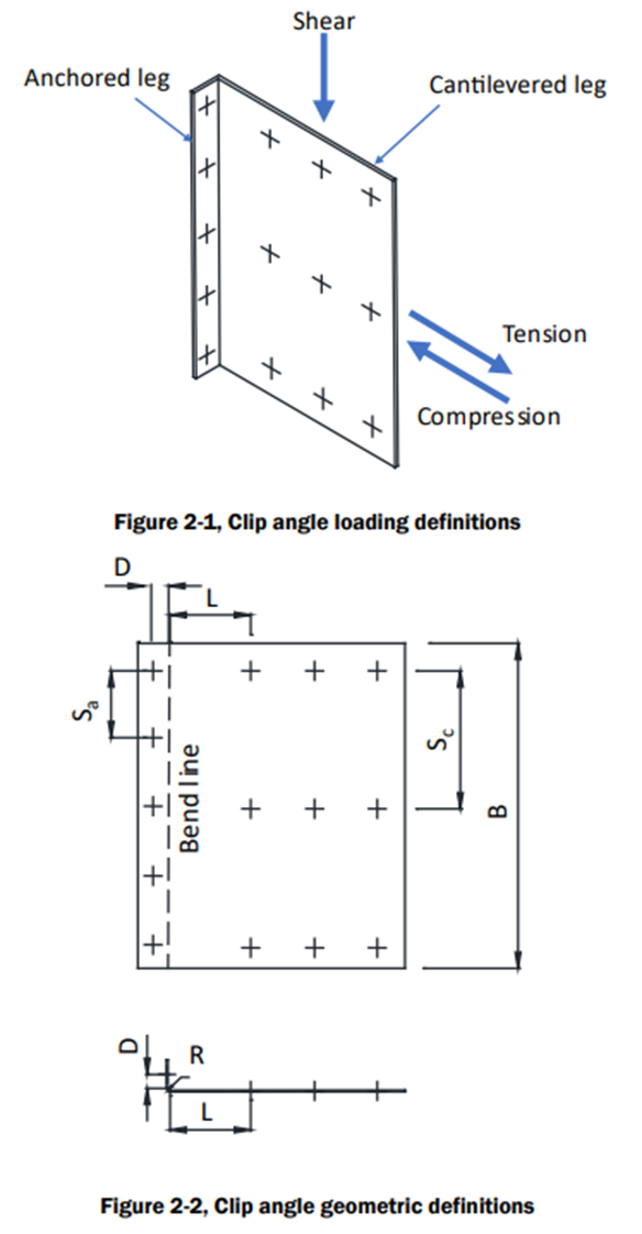
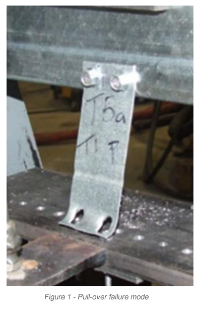
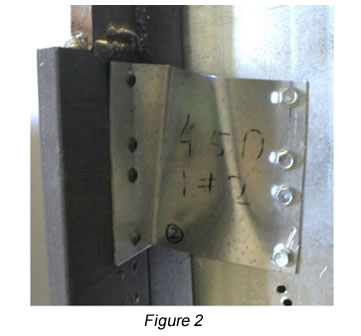
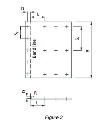
When subjected to a shear load (Figure 1), a clip angle is structurally analogous to a short cantilever beam. Based on research at the University of North Texas, the typical clip angle failure occurs in a panel of length L by depth B (Figures 2 and 3). Thus, the aspect ratio for the failure panel is defined as L/B. A beam is generally regarded as a “deep beam” when its shear span-to-depth ratio, L/B, is < 2.0. Because a clip angle may typically have an L/B ratio equal to or less than 2.0 they exhibit behavior consistent with a deep beam. Also, as defined by AISI D114, the equations are limited to clips having L/B < 1.4.
The main difference between a shallow beam (typical floor joist or curtain wall stud) and a deep beam is that in the case of a shallow beam shear deformations are negligible and could be ignored while shear deformations must be considered in the analysis and design of a deep beam. Because of the geometry of deep beams, their behavior is different from shallow beams. Deep beams are shear dominant and shallow beams are flexure dominant. Thus, the clip angle predominantly fails in shear rather than flexure because it has a small L/B ratio. FEBRUARY 2024
JANUARY 2024
ASTM A1003 was developed to be inclusive of the former ASTM A653, A792 and A875 standards, provide additional options for suppliers, and be consistent with the material requirements of the AISI S240, North American Standard for Cold-Formed Steel Structural Framing. The AISI S240 Section A3.1 User Note states: “ASTM A1003 was developed to be inclusive of ASTM A653/A653M, A792/A492M, A875/A875M and A1063/A1063M standards. For more information see CFSEI Tech Note G801. Therefore, products furnished to these material standards meet the requirements of A1003/A1003M.” DECEMBER 2023
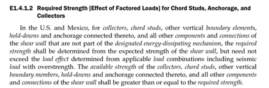
However, In the United States and Mexico, for foundations, the required strength shall be determined from the seismic load effect and need not include the overstrength factor (Ωo) nor consider the expected strength of the seismic force-resisting system unless otherwise specified in the applicable building code. The following User Note has been adopted for the next edition of AISI S400: “In the United States and Mexico, the design of the foundation itself need not consider overstrength or expected strength. However, hold-downs and anchorage into the foundation are capacity protected components. Design of these components, including limit states associated with failure of the foundation material (e.g. concrete breakout, side face blowout, anchor pullout and pryout) must meet the required strength provisions of Section B3.” A similar user note has not been adopted for the next edition of AISI S240 because S240 is limited to design for an R value of 3. NOVEMBER 2023
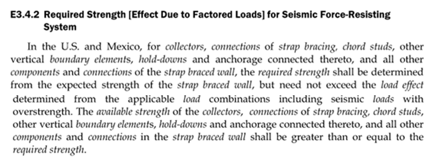
In AISI S400:
S240 and S400 do not have a requirement. However, good practice would recommend staggering joints no matter what orientation of the panels. OCTOBER 2023
SEPTEMBER 2023
AUGUST 2023
JULY 2023
|
||||||||||||||||||||||||
 QUESTION: Why does the “Allowable Screw Shear and Tension Capacities” table in the SFIA “Technical Guide for Cold-Formed Steel Framing” list the Fy and Fu values the same (i.e., 33 ksi) for 18, 27 and 30 mil material thicknesses?
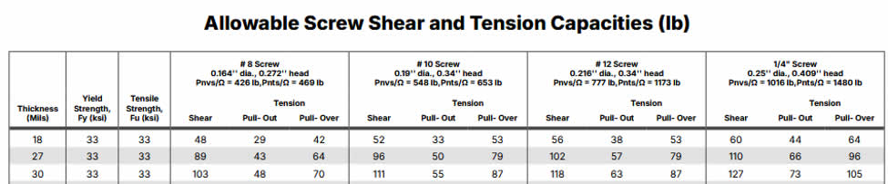
 ANSWER: Material thicknesses 18, 27, and 30 mil steels are used for nonstructural framing applications. The North American Standard for Cold-Formed Steel Nonstructural Framing, AISI S220, Section A3.1 stipulates the following:
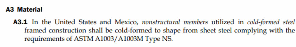


 Splicing of a strap is not prohibited in either AISI S240,
Free Publications

Latest News
- Updated - Tech Note F501-26: Cold-Formed Steel Truss to Bearing Connections
- Updated - Tech Note L200-26: Roof Anchorage Forces: MWFRS or C&C
- CFSEI Names Benjamin W. Schafer, Ph.D., P.E., F.SEI, Recipient of the 2026 John P. Matsen Award for Destinguished Service
- CFSEI Announces Winners of 2026 CFSEI Creative Detail Awards
- CFSEI Announces Winners of 2026 CFSEI Design Excellence Awards
Upcoming Events
Wed Aug 26, 2026Webinar on the Roles and Responsibilities for Success with CFS Framing Category: Events |
Tue Oct 6, 202625th Wei-Wen Yu International Specialty Conference on Cold-Formed Steel Structures Category: Events |
View Full Calendar
Announcements
Press Release! • June 9, 2026
CFSEI Announces Winners of 2026 Design Excellence and Creative Awards
Press Release! • June 8, 2026
CFSEI Names Benjamin W. Schafer, Ph.D., P.E., F.SEI, Recipient of the 2026 John P. Matsen Award for Destinguished Service
Press Release! • April 7, 2026
CFSEI to Host Webinar on Radiused Cold-Formed Steel Structure Design on April 30, 2026
Press Release! • March 20, 2026
CFSEI Announces the Winners of 2026 CFSEI Expo Stipend Program
Press Release! • March 18, 2026
CFSEI Announces the Winners of 2026 Student Competition on Cold-Formed Steel Design