|
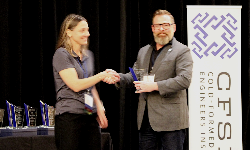
2026 CFSEI DESIGN EXCELLENCE AWARD WINNER
THIRD PLACE - COMMERCIAL
INDUSTRIALIZED CONSTRUCTION SOLUTIONS, INC.
ORLANDO HEALTH BAYFRONT MEDICAL PAVILION
ST. PETERSBURG, FLORIDA
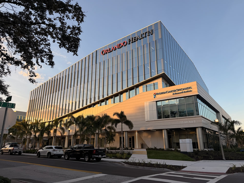
Olando Health Bayfrong Medical Pavilion
615 7th Street S
St. Petersburg, FL 33701
Completion Date: December 2025
Owner: Orlando Health
Architect of Record: HDR
Engineer of Record for Structural Work: Walter P Moore
Cold-Formed Steel Specialty Engineer: Industrialized Construction Solutions, Inc.
Cold-Formed Steel Specialty Contractor: KENPAT
Award Entry Submitted by: Matthew Comber, Industrialized Construction Solutions, Inc.
Project Background
The Orlando Health Bayfront Pavilion is a six-story, 132,000-square-foot healthcare facility
located in downtown St. Petersburg, Florida. Constructed on an active hospital campus in a dense urban environment, the project operated under a highly compressed schedule. The team also managed significant site and sequencing constraints.
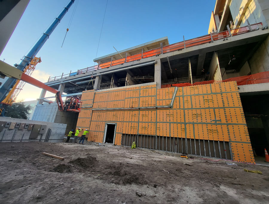
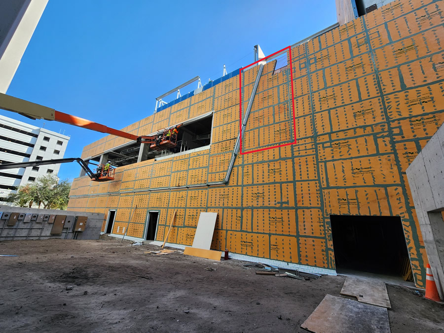
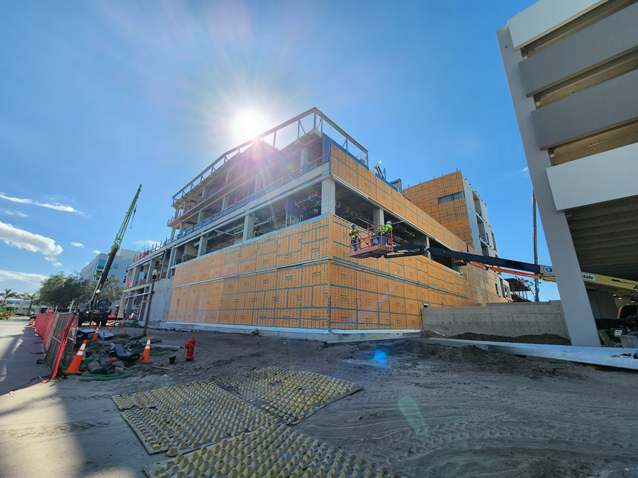
The exterior envelope incorporates a prefabricated panelized cold-formed steel (CFS) framed curtainwall system. The system supports architectural cladding and high-performance enclosure assemblies suitable for a coastal healthcare facility.
KENPAT engaged Industrialized Construction Solutions (ICS) to rapidly pivot an already partially developed CFS curtain wall framing approach. The team aligned the design with preferred prefabrication and erection practices, project budget and erection timeline and sequencing.
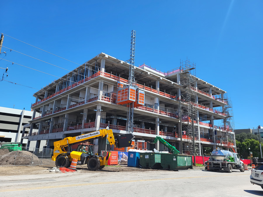
Crews had already constructed portions of the PT concrete primary structure and façade support conditions. KENPAT had less than six weeks to begin curtain wall erection.
As a result, the team re-envisioned the exterior framing strategy. They accommodated fixed geometries, already cast anchorage embeds and evolving field conditions.
ICS’s scope included delegated engineering and design of the CFS curtain wall framing. The team coordinated with the SEOR, AOR, GC and architectural cladding contractor N-RG. They supported a prefabricated panelized delivery strategy, including production files and prefab assembly designs. ICS also provided ongoing engineering support throughout fabrication and installation.
Design Challenges and Solutions
Urban Constraints and Project Sequencing
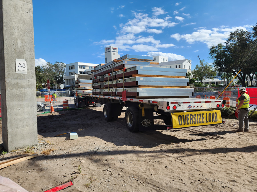
Active pedestrian and vehicular routes bordered the Bayfront Pavilion footprint on two sides. A third side abutted an active parking structure, and a fourth an adjacent construction site. This left limited space for material staging, site access and concurrent trade operations.
Schedule impacts from other trades compounded these urban constraints. The disruptions affected typical sequencing and required the curtain wall system to be delivered and installed out of sequence relative to standard panelized construction workflows.
The curtain wall framing was engineered and detailed to accommodate alternate installation sequences while maintaining structural clarity and constructability. Tolerance management, connection accessibility and erection clearances were incorporated directly into the design. This approach allowed prefabricated components to be installed without conflicts with adjacent work. It also enabled continued progress on the enclosure despite site and schedule limitations.
Redesign Around As-Built Structural Conditions
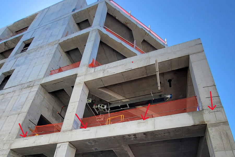
More than three stories of the PT concrete structure and cast-in anchorage embedments were already in place before ICS was engaged for the curtain wall redesign. As a result, the exterior framing system had to respond to fixed geometries and attachment conditions that constrained conventional load paths.
These interfaces varied across the façade. They limited standardization and introduced a range of structural capacity and tolerance considerations. And no additional post-installed anchorage was permitted to maintain the integrity of the PT concrete superstructure.
Rather than rely on idealized assumptions, the team developed a redesigned system using measured field conditions and as-built information. They used this data to define force transfer and attachment strategies.
Each interface was evaluated individually. The team also customized framing strategies and developed details to redistribute loads into adjacent framing members where embed locations or capacities were restrictive. This approach preserved the structural integrity of both the superstructure itself and the anchorage points. It also minimized field rework and maintained alignment with architectural intent.
Prefabrication and Interface Validation
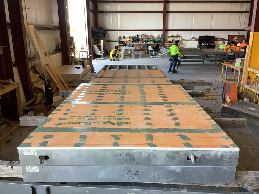
The team executed the exterior curtainwall using prefabricated wall panel units. The fabricator incorporated CNC-rolled and pre-tooled CFS framing, sheathing, insulation and waterproofing. This delivery method increased emphasis on dimensional accuracy, connection clarity and interface coordination across trades.
Rapid design-assist coordination and full-scale mockups allowed the team to validate framing geometry, attachment details and tolerances across multiple trades before full production. The team used these exercises to refine connection logic and panel geometry. This improved fabrication efficiency and field fit-up, and reduced installation risk.
ICS developed the design concepts in a BIM environment. The firm used self-developed digital data conversion tools to communicate directly with KENPAT’s CNC roll forming and pre-tooling equipment. This approach reduced the design-to-fabrication timeline and nearly eliminated the risk of human error associated with the traditionally manual, PDF-based process of translating design intent to fabricated product.
Creative Detailing for As-Built Embed Conditions
In multiple instances, pre-installed embed locations and load capacities conflicted with desired curtain wall framing load paths. The team resolved these conditions with solutions that respected fixed constraints while maintaining structural performance and constructability.
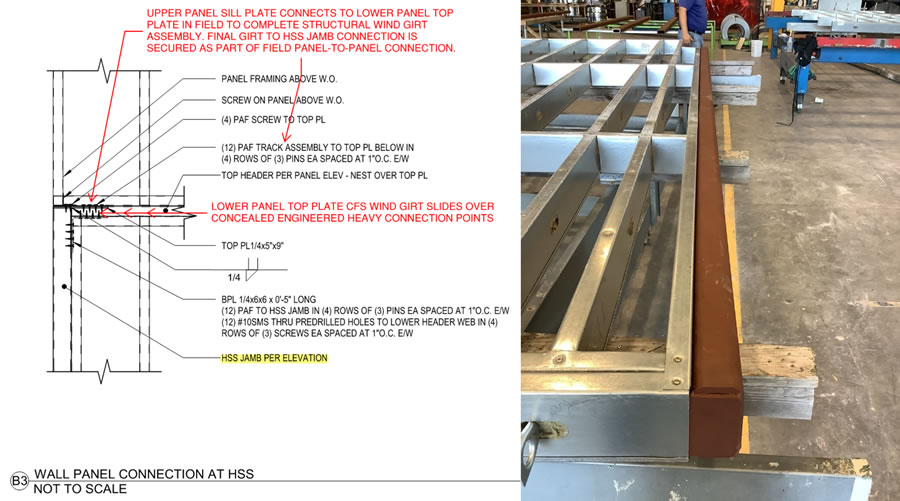
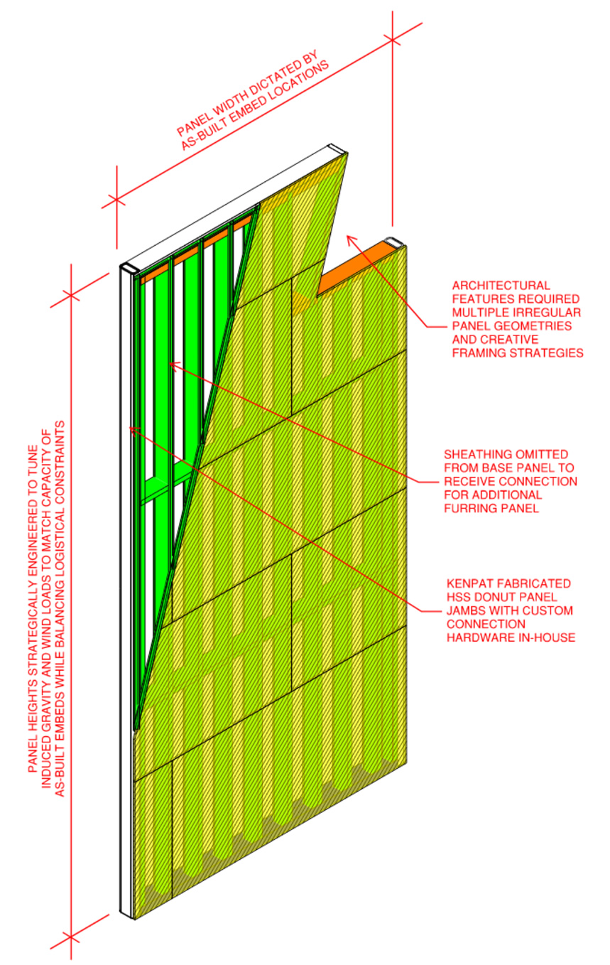
The team developed custom hybrid HSS “donut” panels to allow framing members to bypass fixed embed locations while maintaining alignment and continuous load paths. This configuration improved material and fabrication efficiency. It remained flexible where geometry could not change. It also accommodated as-built conditions without overstressing anchors.
As-built embed locations largely drove panel widths. The team tuned panel heights to match induced wind and gravity loads to anchor capacity. Architectural feature locations and control joint requirements largely drove panel elevation relative to anchor locations.
The team engineered the donut frames to transfer panel framing loads to anchorage locations with maximum material efficiency. They leveraged KENPAT’s ability to roll certain CFS profiles and fabricate red iron assemblies in-house.
The resulting detail turned highly constrained conditions into a refined, repeatable design solution. The team fabricated it quickly in a single facility on a tight delivery timeline while maximizing KENPAT’s production capabilities.
Field Support and Out-of-Sequence Installation
As construction progressed, schedule disruptions required crews to install portions of the prefabricated curtain wall system out of sequence. This atypical condition required continued engineering involvement to maintain framing integrity and load paths despite the nonstandard erection order.
The team provided responsive engineering support, clarified field questions quickly and coordinated closely with fabrication teams. This approach allowed the system to adapt without compromising performance or impacting the schedule. The team preserved design intent while accommodating real-time construction constraints. The approach enabled enclosure work to continue and prevented further schedule impacts.
Environmental Resilience
During construction, Hurricane Milton struck the project site directly. The storm caused significant regional damage. It included the collapse of the roof at Tropicana Field and a tower crane at a nearby construction site. Both were within one mile of the Bayfront site.
Despite these impacts, the project site sustained no damage. Curtain wall fabrication and installation proceeded without hurricane-related delays. The exterior framing system performed as designed under these conditions. This performance validated the design assumptions and execution practices.
Outcome
Despite late engagement, fixed structural constraints and disrupted sequencing, the team delivered the exterior CFS curtain wall system on time and on budget. They also managed limited laydown space and an accelerated schedule.
The Orlando Health Bayfront Pavilion demonstrates how design excellence in cold-formed steel emerges through disciplined engineering and creative detailing. It also reflects integrated problem solving across engineering, fabrication, erection, logistics and scheduling.
|