
|
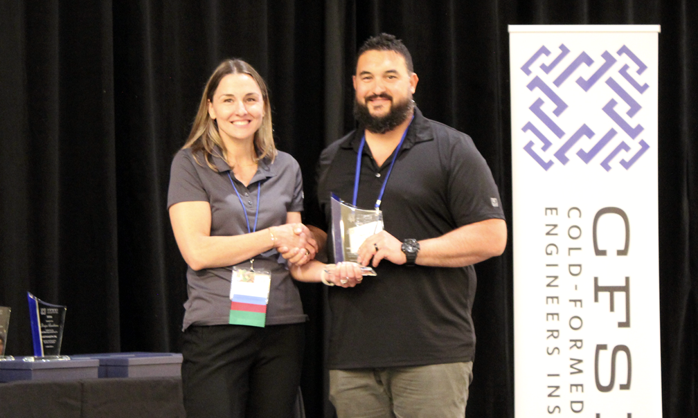
2026 CFSEI DESIGN EXCELLENCE AWARD WINNERFIRST PLACE - MUNICIPALLOCHSA ENGINEERING, LLC
|
||||
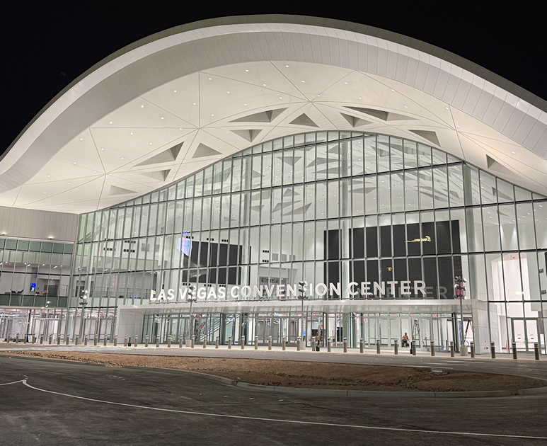 Las Vegas Convention Center Renovation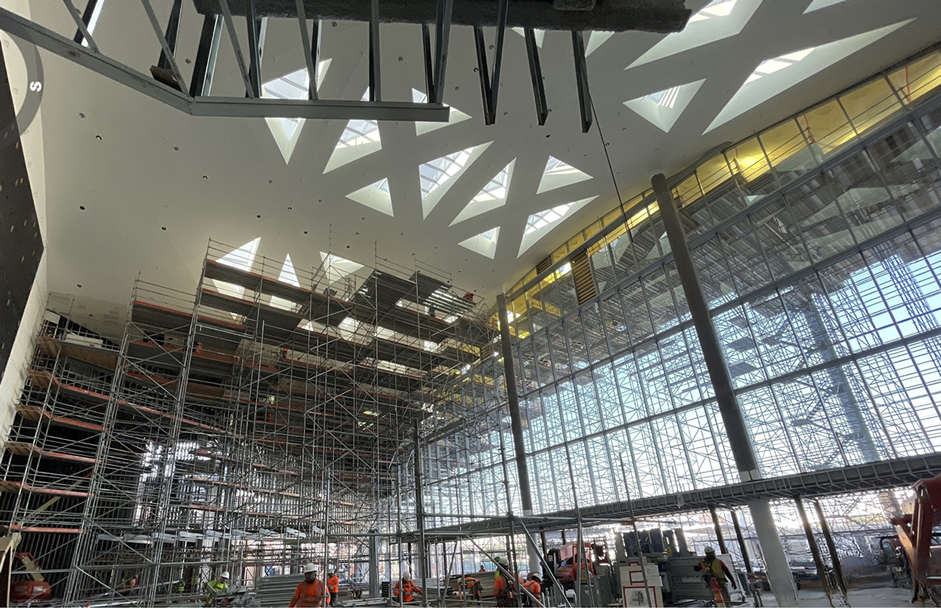
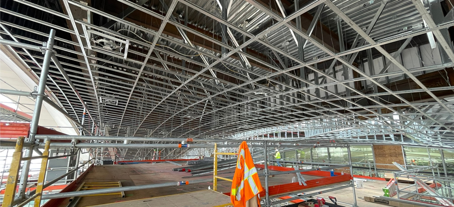
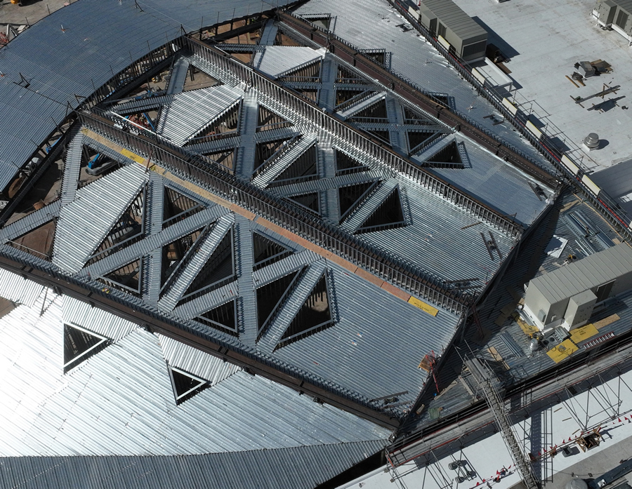
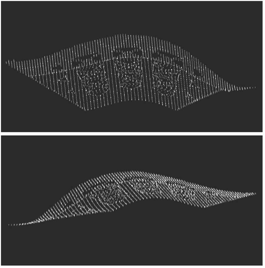
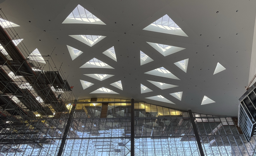
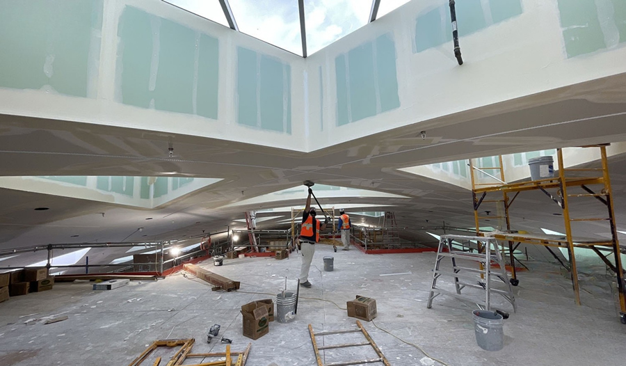
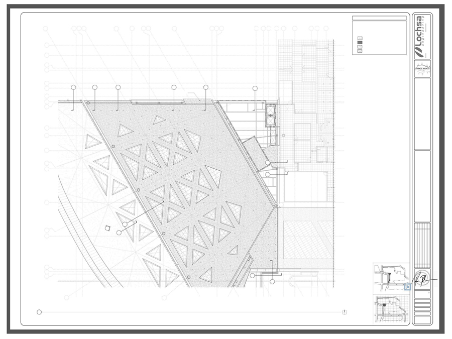
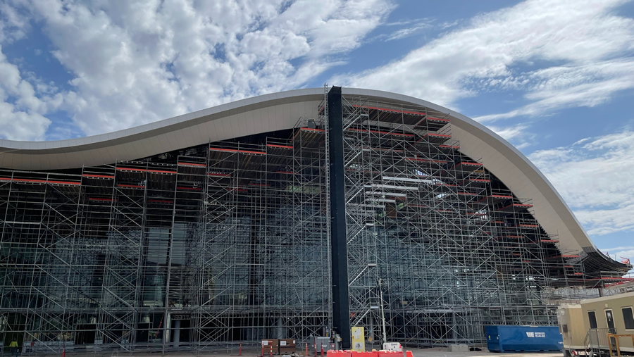
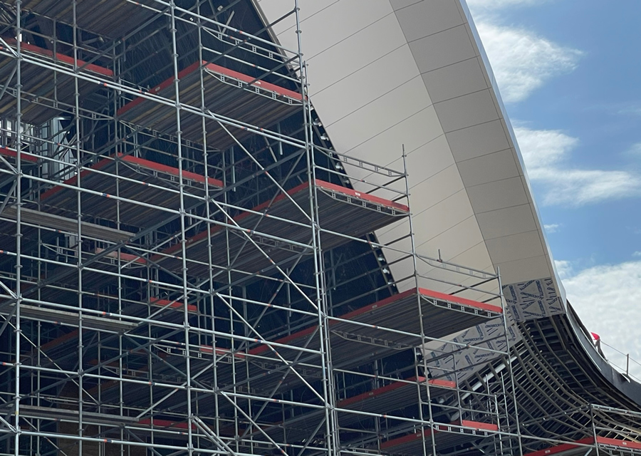
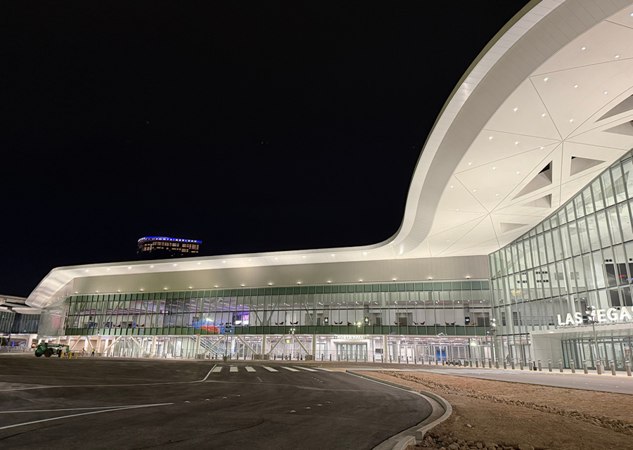
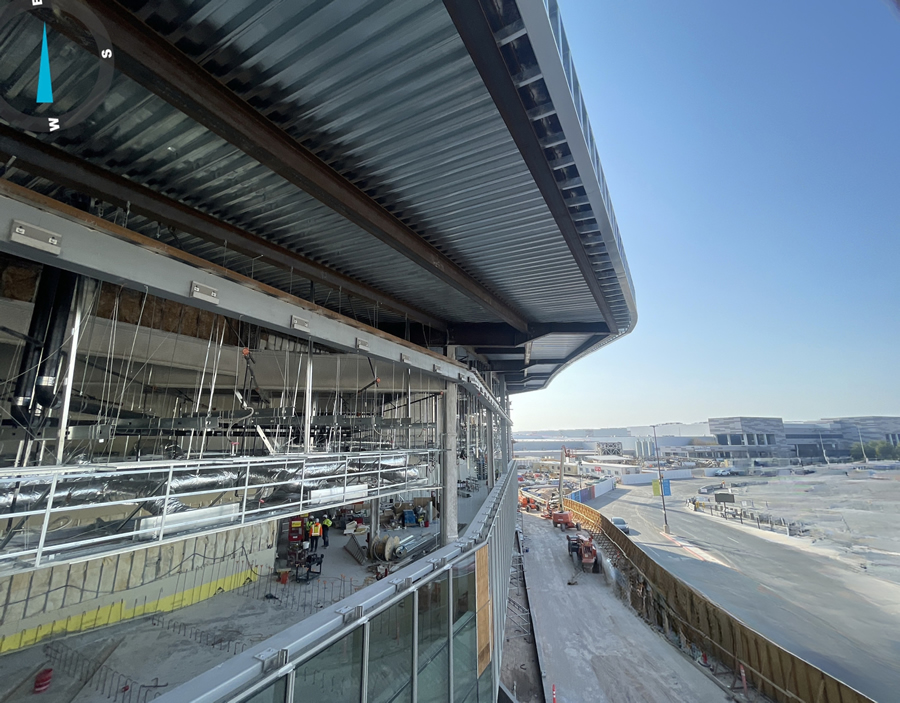
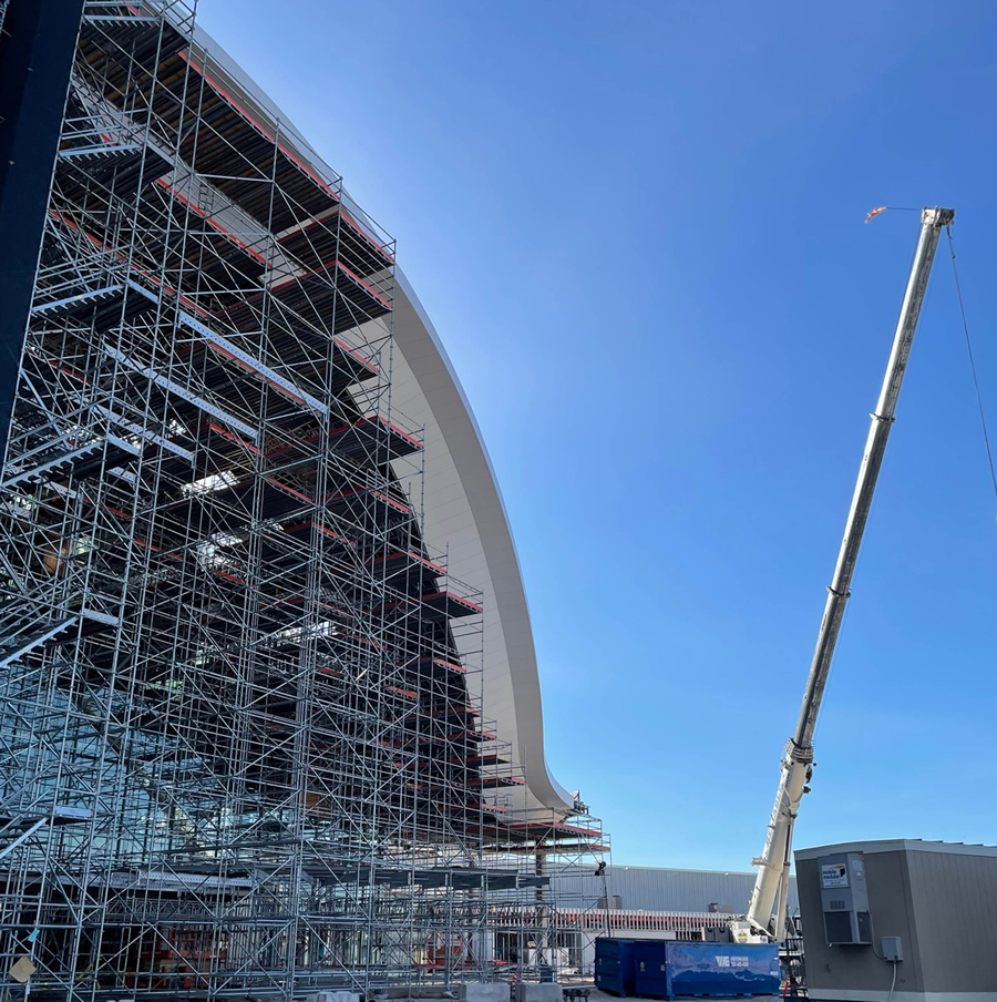 Perimeter soffits required framing that followed long, radius-driven curves. The framing also shifted pitch and angle to match the building’s evolving roof geometry. These conditions produced compound curves that had to align seamlessly with façade transitions and weather barrier interfaces.
 |
 |
 |
|
Existing Structure and MEP Interference Zones
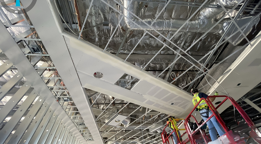
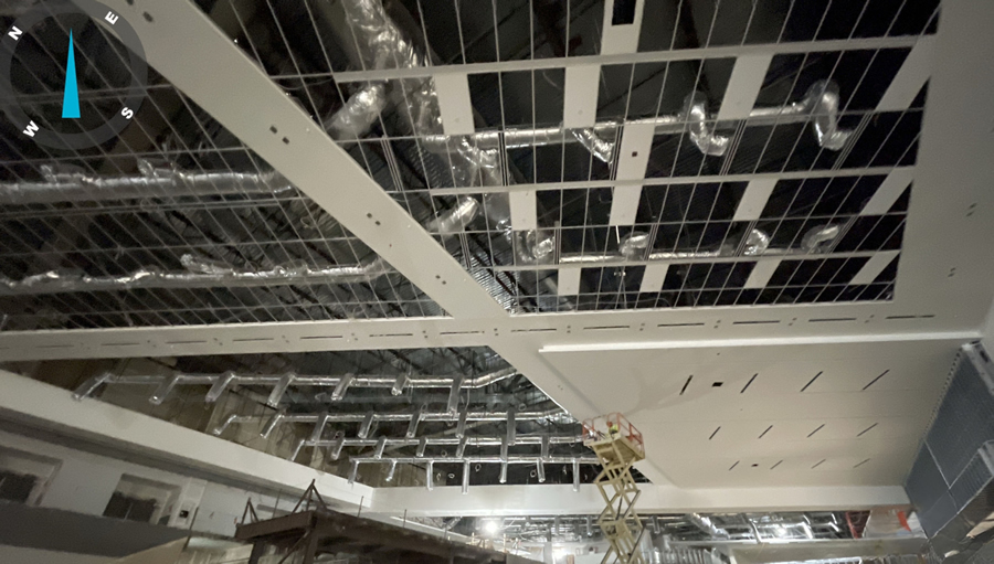
Multiple areas of the existing building contained dense MEP congestion and legacy structural elements that conflicted with the proposed soffit and bulkhead framing. Standard framing approaches could not accommodate overlapping systems or maintain required clearances. As a result, traditional bulkhead layouts were not constructible.
Solution
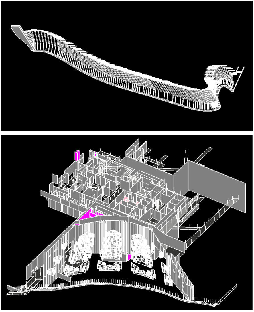
The Lochsa Engineering team used current CFS structural design programs, BIM and VDC software to develop a specialized bulkhead framing system. The system uses 4'-0" on‑center vertical drops. This created standardized pathways for mechanical, electrical and plumbing systems while maintaining critical ceiling alignments.
Every element of the bulkhead was modeled and designed in detail to ensure full constructability, including:
- Accurate and proficient CFS member and connection designs
- Exact stud and track placement for each 4' drop zone
- Intermediate braces and blocking required for structural continuity
- Integration with existing structure, MEP obstructions and clearance requirements
- Verification of member spacing, brace connectivity and attachment logic
- Coordination of framing depth to maintain ceiling alignment across interference areas
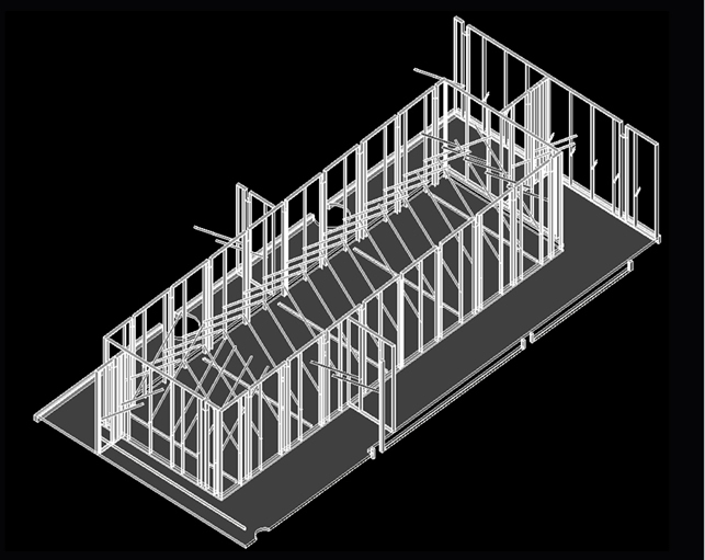
The structural engineering design, combined with the digital coordination effort, became a continuous, collaborative process involving Lochsa Engineering, the CFS contractor, general contractor and project architect.
This daily refinement allowed the team to identify and resolve issues early, before they impacted field installation. It resulted in fewer surprises, minimized costly changes, reduced rework and smoother sequencing through the most technically demanding areas of the remodel.
In the end, the structural engineering design and VDC effort did more than support construction, it shaped it. The high-fidelity models eliminated guesswork, ensured predictable installation and enabled the framing teams to work confidently within extremely congested conditions.
The payoff was substantial: faster layout, fewer adjustments and zero-dimensional change orders. The project matched the performance achieved on other complex systems, such as the Ribbon Roof. The project was precise and well-coordinated. This is what good CFS design looks like.
Conclusion
Lochsa accurately addressed three design challenges:
- Dual-Curved Sno-Cone Lobby Ceiling
- Curved Exterior Soffits with Compound Geometry
- Existing Structure and MEP Interference Zones
By leveraging precise structural engineering detailing and BIM/VDC modeling, the Lochsa team translated three complex design challenges into coordinated, constructible cold-formed steel solutions. These included the dual-curved lobby ceiling, compound-geometry exterior soffits and dense existing MEP interference zones.
Through early digital problem solving, fabrication-level detailing and continuous collaboration, the team minimized rework, eliminated dimensional conflicts and delivered predictable framing outcomes across critical areas.
Free Publications

Latest News
- NEW - Tech Note W401-26, Brace Design Using AISI S915
- Due October 15 - Presentation Abstracts for 2027 CFSEI Expo
- Updated - Tech Note F501-26: Cold-Formed Steel Truss to Bearing Connections
- Updated - Tech Note L200-26: Roof Anchorage Forces: MWFRS or C&C
- CFSEI Names Benjamin W. Schafer, Ph.D., P.E., F.SEI, Recipient of the 2026 John P. Matsen Award for Destinguished Service
Upcoming Events
Thu Oct 29, 2026Webinar on Structural Floor Systems for Cold-Formed Steel Structures Category: Webinar |
View Full Calendar
Announcements
Press Release! • June 9, 2026
CFSEI Announces Winners of 2026 Design Excellence and Creative Awards
Press Release! • June 8, 2026
CFSEI Names Benjamin W. Schafer, Ph.D., P.E., F.SEI, Recipient of the 2026 John P. Matsen Award for Destinguished Service