|
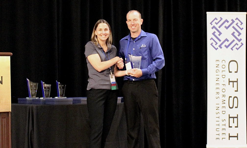
2026 CFSEI CREATIVE DETAIL AWARD WINNER
THIRD PLACE
McCLURE
LEGENDS 267 APARTMENTS
KANSAS CITY, KANSAS
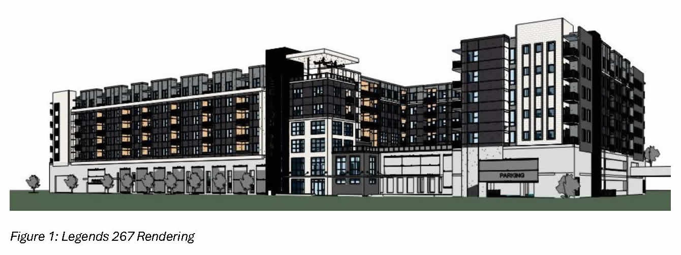 Legends 267 Apartments Legends 267 Apartments
1879 Village West Parkway
Kansas City, KS 66111
Completion Date: 2024
Owner: Beck-Cal Development
Architect of Record: Rosemann Associates
Engineer of Record for Structural Work: McClure
Cold-Formed Steel Specialty Engineer: Jesse Barnes, McClure
Cold-Formed Steel Specialty Contractor: Steve Nienke, Midwest Drywall
Award Entry Submitted by: Marcus Himmelberg, McClure
Project Background
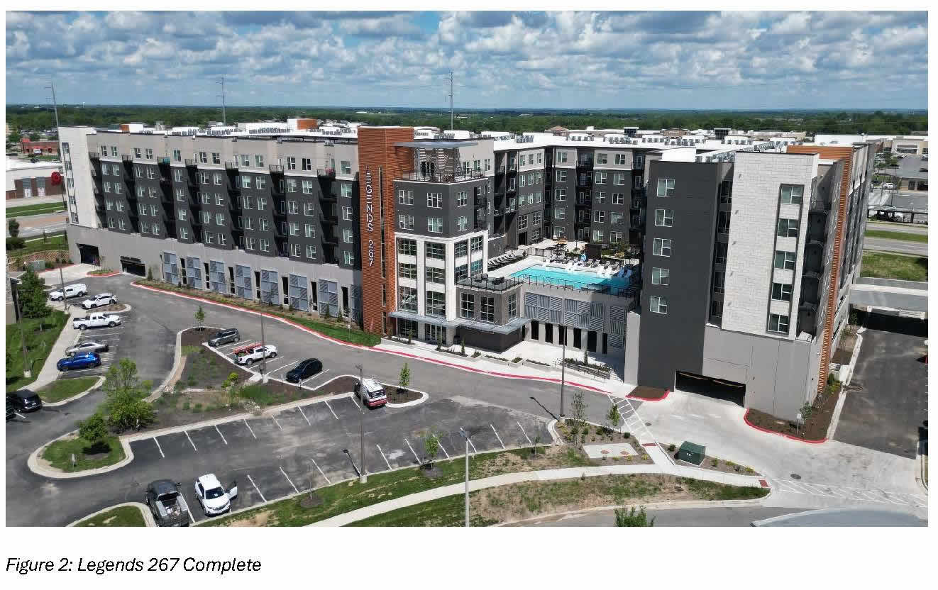
McClure served as the specialty cold-formed steel (CFS) engineer for the Legends 267 Apartments. The project is a five-story CFS load-bearing structure over a three-story precast parking garage. The residential portion encompassed approximately 300,000 square feet above the 240,000-square-foot parking garage.
The site sits in the Legends district west of downtown Kansas City. It is adjacent to Children’s Mercy Park and the Kansas Speedway. The development includes 267 luxury studio, one-bedroom and two-bedroom units. It stands as the only urban-style mid-rise apartment building in the area.
The Legends 267 project marked a shift toward high-density, urban-style living within a traditionally suburban entertainment corridor. By using a CFS load-bearing system, the design team optimized the structural footprint. This approach allowed five levels of residential space to sit efficiently above the precast parking podium.
The system maximized allowable height and unit density. It also provided a durable, noncombustible solution suited to a modern luxury mid-rise. The project integrates with the surrounding sports and racing venues. It serves as a residential hub for the district.
Design Challenges and Solutions
The contractor and developer selected a precast garage early in the design process. They considered other structural systems, but the team selected cold-formed steel for the residential structure above the podium.
The primary challenge was how to transfer loads from a five-story structure onto a precast podium. Unlike typical wood framing, the CFS structure is panelized. This required tight construction tolerances and limited field adjustment. Crews did not have the flexibility to cut and fit members in the field.
Additionally, the team identified specific CFS bearing walls and strap-braced CFS shear walls. These walls supported the five-story structure above the podium in place of distributing loads through all walls.
This posed multiple problems with the precast systems for the podium level. If the precast could not handle the CFS shear wall end reactions, the team would have needed an alternate lateral system. Options included concrete masonry units (CMU) or concrete shafts. These alternatives would have added significant cost. McClure evaluated CFS lateral shear walls as a viable solution for the five-story structure on precast.
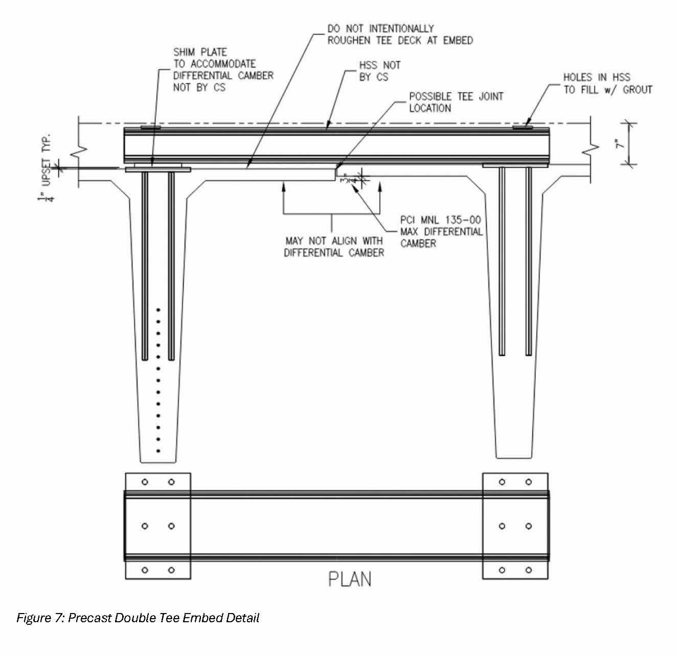
The precast podium created additional challenges for the CFS lateral system. Loads exceeded the capacity of standard precast double-tees. McClure performed iterative analysis of the shear wall layout to reduce reactions to the podium. The team also developed details to accommodate camber in the precast panels. These details allowed installation tolerances while distributing loads to avoid overstressing the panels.
McClure worked closely with the precast engineer. The teams evaluated the maximum capacity achievable with the precast double-tee sections.
Once the team reduced reactions to levels acceptable for the precast spans, challenges remained with the reaction locations. The double-tees were spaced at regular intervals. As a result, the webs of the W-tees occurred at fixed locations along the garage.
The CFS shear wall locations were governed by the residential unit layout within the building. This condition often placed shear wall end reactions over the flanges of the precast sections.
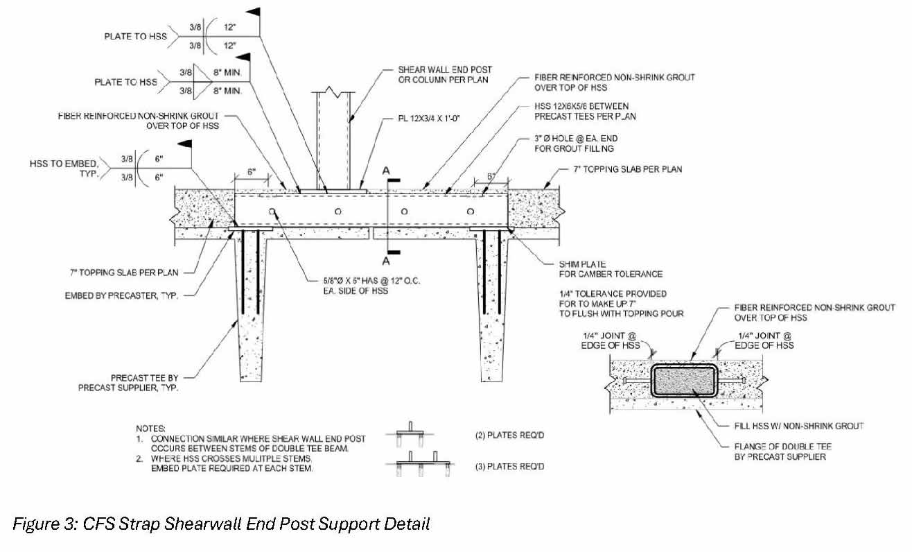
The double-tee flanges had a minimum thickness. They could not handle the punching shear from the CFS shear wall end posts. The team could not place concrete between the stems of the double tees due to the randomness of the locations. It would have required casting every double-tee section as a unique piece. Instead, McClure created a detail that would handle the shear wall reactions and bridge the distance between the double-tee stems.
McClure quickly realized the precast podium created another problem. The precast double-tees were cast with camber in the sections. Early on, McClure determined that a topping would be required over the precast structure. A typical topping would be 2” to 4” thick. But a greater topping depth was required, given the shear wall end post support detail developed.
McClure worked with the precast engineer to determine an estimated camber before and after the topping slab was poured, so the CFS panels could be placed on a level surface. Gaps of several inches under the wall panels would have occurred without this analysis.
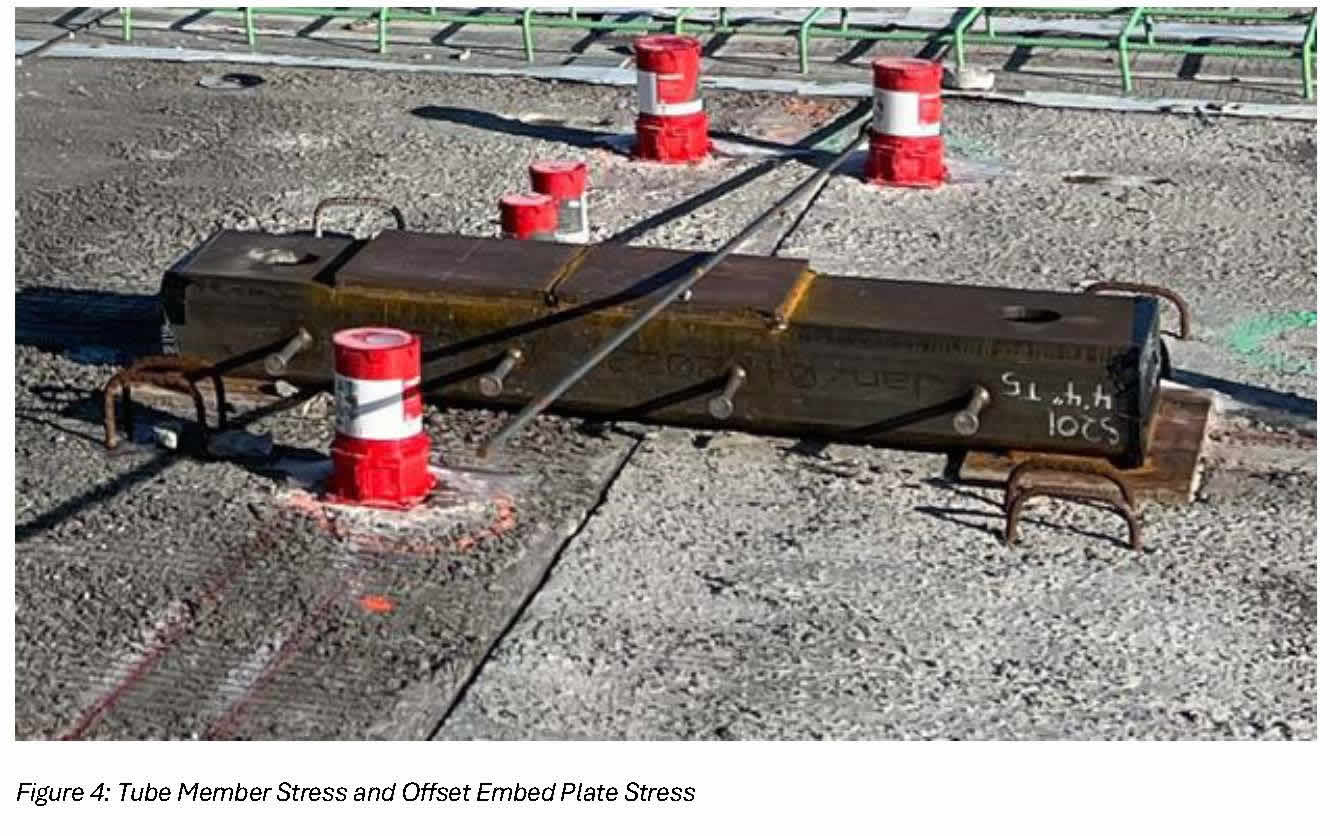
Instead, McClure developed the shimming requirements within the shear wall support detail. Because the shear wall end posts had to be attached to embeds for the uplift forces in the CFS shear wall end posts, it was critical the embed detail accommodate the proper height and topping slab. The detail had to allow for the physical connection of the shear wall end post to the carrying tube member.
A base plate was used to prevent local stress issues in the tube member and to ensure the plate remained exposed when the topping slab was poured. This allowed the tube to be fully covered within the floor so there were no areas of steel exposed in the finished floor space.
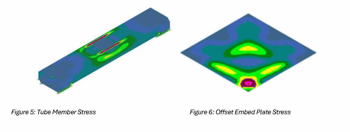
Lastly, the detail had to transfer shear forces out of the CFS shear walls. The team could not align shear walls in the precast garage with the CFS shear walls above the podium. As a result, the podium diaphragm transferred lateral forces.
McClure designed a detail that used headed studs along the sides of the tube members. These studs transferred loads into the topping slab. The studs carried the CFS shear wall end reactions into the precast topping slab. The topping slab then transferred the loads to the precast shear walls.
|