|

2026 CFSEI CREATIVE DETAIL AWARD WINNER
SECOND PLACE
EXCEL ENGINEERING, INC.
RUTTERS NO. 82
ALTOONA, PENNSLYVANIA
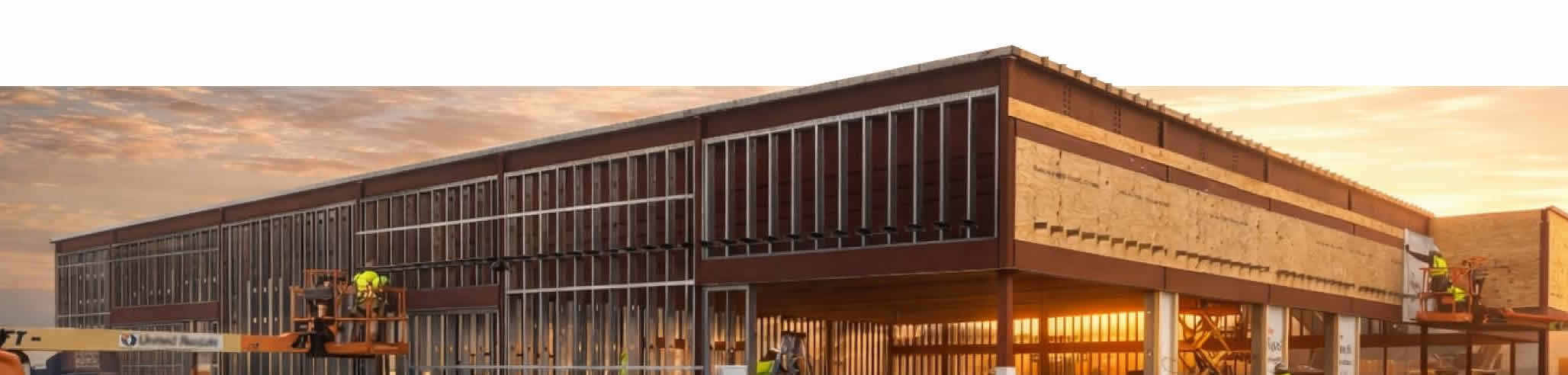
Rutters No 82
432 Sabbath Rest Road
Altoona, PA 16601
Completion Date: 2024
Owner: Rutter's
Architect of Record: Mula Group
Engineer of Record for Structural Work: Onyx Design & Consulting
Cold-Formed Steel Specialty Engineer: Joe Wilkum, Excel Engineering, Inc.
Cold-Formed Steel Specialty Contractor: Dave Dillen, Lawruk Builders, Inc
Award Entry Submitted by: Joe Wilkum, Excel Engineering, Inc.
Project Background
In August 2023, Excel Engineering was hired to design the exterior cold-formed steel (CFS) framing for the Rutter’s #82 project in Altoona, Pennsylvania. The project involved a single-story structure measuring approximately 100 by 100 feet.
The roof structure used structural steel beams spaced at approximately 5 feet on center. Perimeter structural steel beams supported these members. Structural steel columns supported the perimeter beams.
The team designed the CFS as non-load-bearing infill framing. The framing sits on the foundation and attaches to the underside of the perimeter beams using slip connections. (See SNIP A.)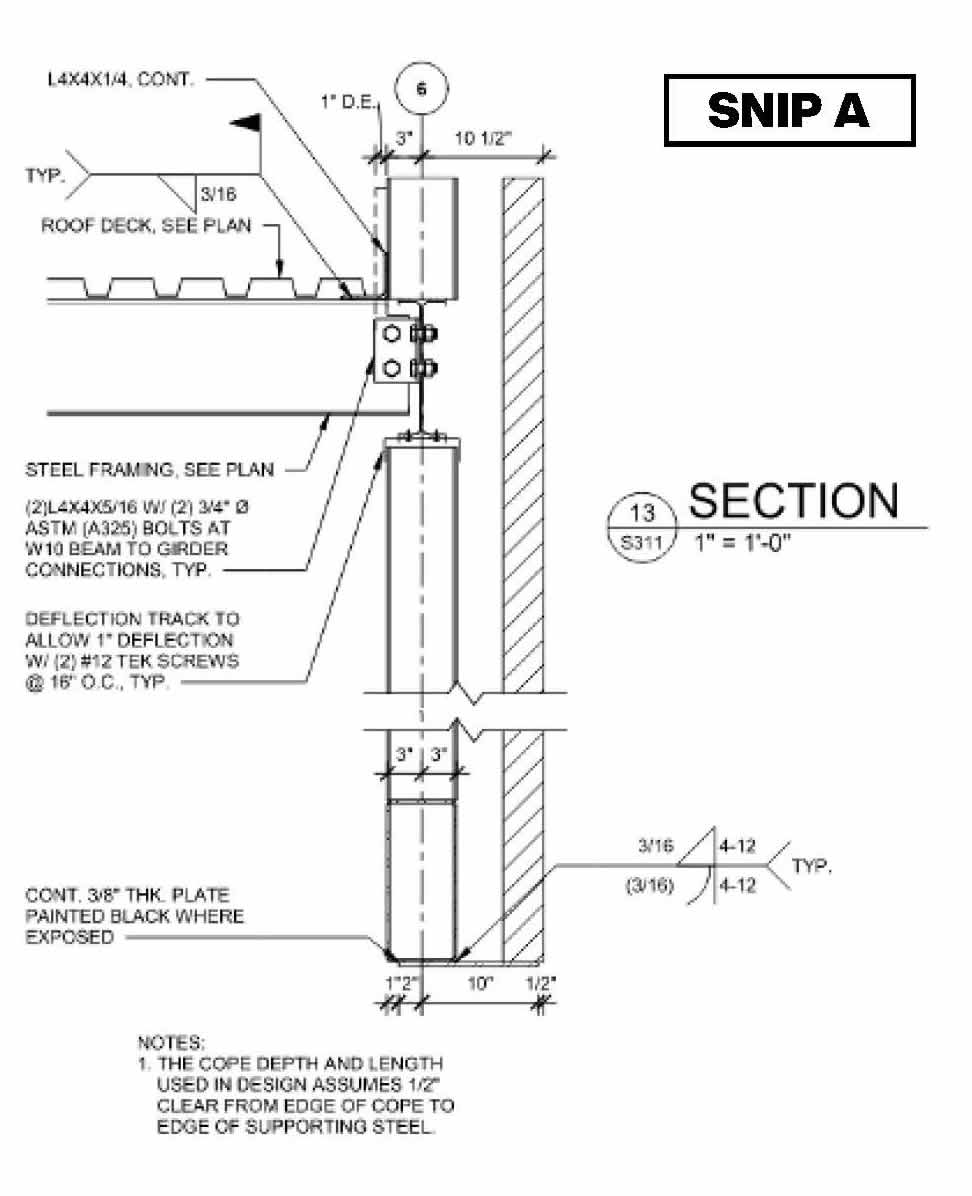
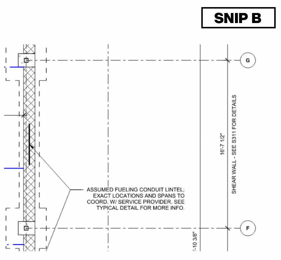
Upon closer review of the structural plans, the team identified plywood shear walls on three sides of the building. The fourth side used moment frames. (See SNIP B.)
The details referenced slip track at the underside of the beam.
Red Flag: Slipped Shear Walls Do Not Work
The engineer contacted the EOR, who insisted on using slipped shear walls. At the time, little guidance existed on the design or application of slipped shear walls. I proposed a concept to address slip and shear transfer. At the time, we both felt comfortable with the detail.
Design Challenges and Solutions
April 2024 (Non-Bearing Shear Wall Webinar)
Nine months later, the Excel Engineering specialty engineer attended a CFSEI online seminar on non-bearing shear walls (NBSW). The seminar stated that NBSWs have limited application and should be used only when absolutely required. These applications include single-story structures, low seismic conditions and low forces. The seminar emphasized that designers must maintain a clear load path when designing NBSW.
“I wish I had known this before the Rutter’s project,” the Excel Engineering designer said.
Postmortem
The day after the seminar, the Excel Engineering specialty engineer performed a postmortem on the project. The seminar did not specifically address the detail, so the designer verified that the design met required considerations.
For the Rutter’s project, the designer developed a wide flange stud to collect shear loads. The stud transfers these loads into the plywood through a slotted slip track. The designer detailed the wide flange stud to lie flat inside the slotted slip track, similar to nested components.
This configuration created the following shear wall load path:
- Steel beam
- Slotted slip track through the screws (slots at 1 inch on center allow flexible screw spacing)
- Wide flange collector (See Detail D in orange)
- Top track (See Detail D in green)
- Plywood sheathing
The seminar summary confirmed that NBSW applications remain limited to specific conditions. The Rutter’s building met these criteria. It is a single-story structure in Seismic Design Category A. At least half of the wall length on three sides functions as shear walls, which keeps loads manageable.
Overall, the detail meets the criteria outlined in the seminar. It resists out-of-plane wind loads and transfers shear loads while accounting for live load deflection. Based on the seminar guidance, the designer recommends adding signage to address future renovations and potential removal of shear wall framing. The designer also plans to include a note in future submittals when NBSW systems are used.
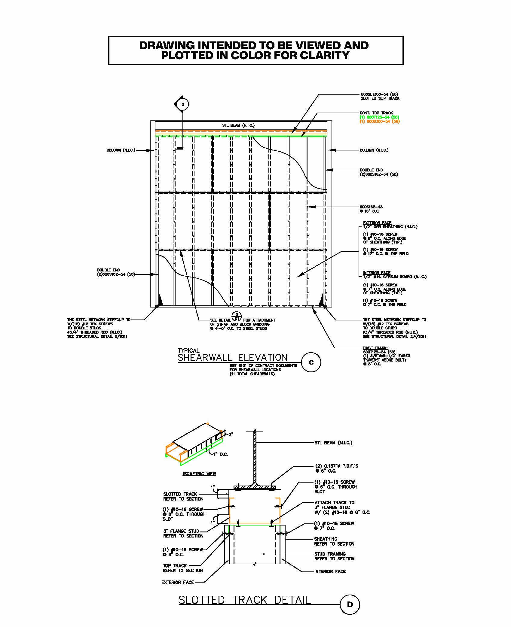
Photo and Details Courtesy of Excel Engineering, Inc.
|