2023 CFSEI DESIGN EXCELLENCE AWARD WINNERS
SECOND PLACE - MUNICIPAL/SPORTS
TACOMA ENGINEERS INC. – CANADA SUMMER GAMES BUILDING
THOROLD, ONTARIO, CANADA
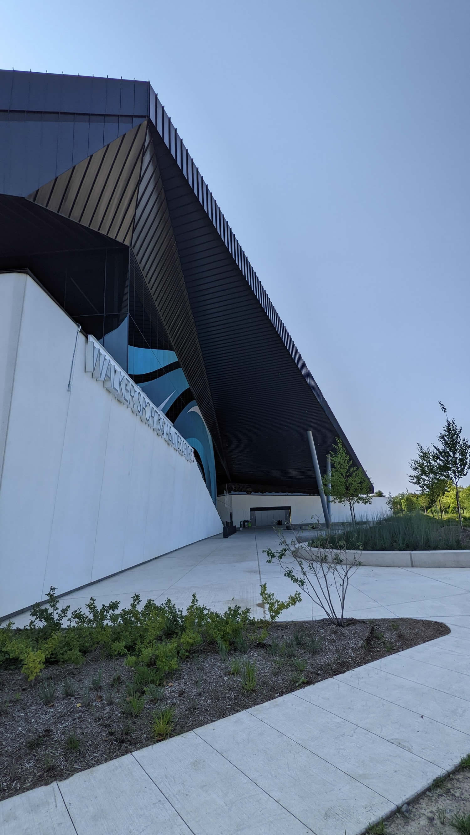 Canada Summer Games Building Canada Summer Games Building
Thorold, Ontario, Canada
Completion Date: 2022
Owner: 2021 Canada Summer Games
Architect of Record: MacLennan Jaunkalns Miller Architects
Engineer of Record for Structural Work: Blackwell Structural Engineers.
Cold-Formed Steel Specialty Engineer: Ignac Zajac, P.Eng. M.A.Sc., Tacoma Engineers Inc.
Cold-Formed Steel Specialty Contractor: Adam Dewitt, Daily Smith Contracting Ltd, Daniel Warren, Daily Smith Contracting Ltd.
Award Entry Submitted by: Ignac Zajac, Tacoma Engineers Inc.
Project Background
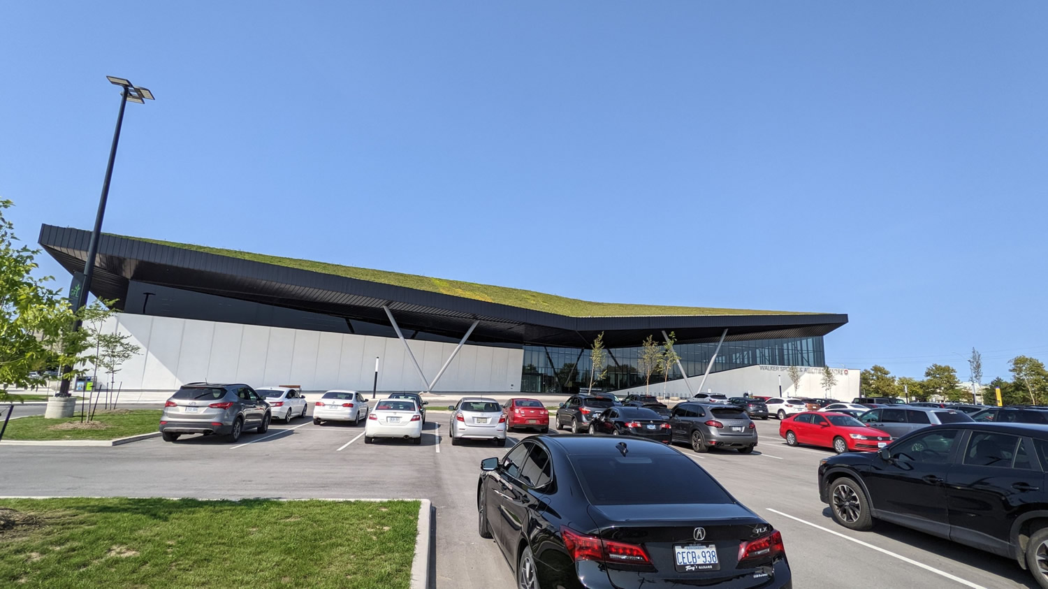
The Canada Summer Games building is a multi-purpose sports facility featuring two NHL-sized ice rinks, a suspended 200m indoor track, a multi-purpose fieldhouse featuring four gymnasiums, a sport performance center and sport offices. The roofs of the overhanging canopies are covered by vegetation. The building footprint is 212,400 sf and consists of two main levels. The building shell consists of structural steel framing. The gravity system consists of structural steel beams, columns and open-web steel joists (OWSI), while the lateral system consists of structural steel braced frames.
Design Challenges and Solutions
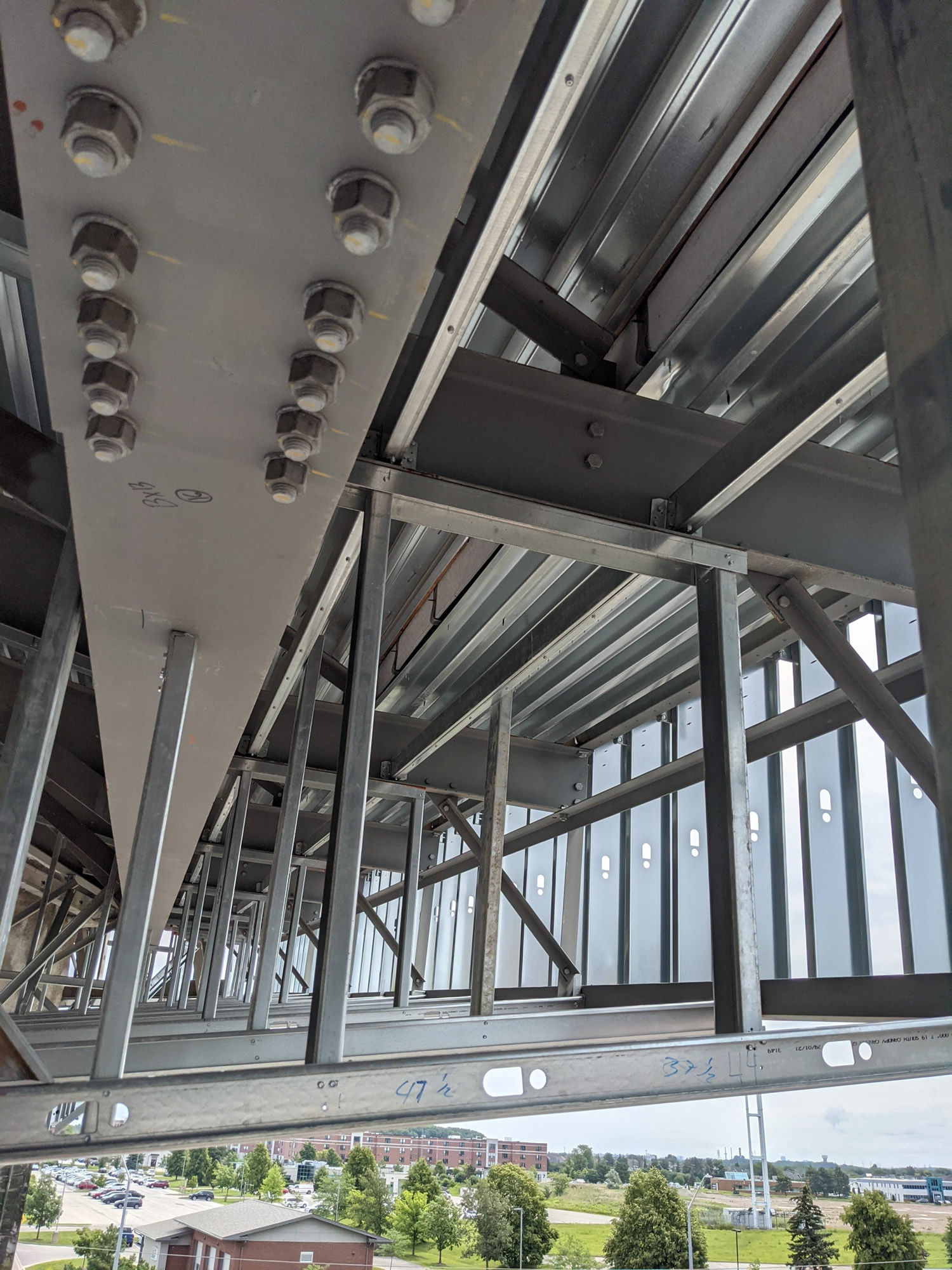 The building consists of large overhanging canopies with sloping soffits. The soffits for the overhanging canopies consist of 1½” prefinished standing seam metal cladding on 1½” metal deck. The cold-formed steel (CFS) scope of work for the project consists of providing the soffit support for the cladding and metal deck at the overhanging canopies. The metal deck required continuous support at a predetermined spacing. The building consists of large overhanging canopies with sloping soffits. The soffits for the overhanging canopies consist of 1½” prefinished standing seam metal cladding on 1½” metal deck. The cold-formed steel (CFS) scope of work for the project consists of providing the soffit support for the cladding and metal deck at the overhanging canopies. The metal deck required continuous support at a predetermined spacing.
The soffits consisted of six main areas with a total area of 34,000 sf, with the largest soffit areas being the north and south soffits at over 10,000 sf each. Each soffit area had unique geometry and sloped in two different directions.
The CFS framing was supported from the structural steel roof structure only. Complicating the matter was the roof framing, which was different at each soffit area. Some areas consisted of OWSJ, while others were HSS trusses, or a combination of OWSJ and steel beams. The roof structure itself was sloped in two different directions, making fit up and connections a challenge. The roof structure was also at a significantly higher elevation than the plane of the soffits requiring all the CFS framing to be suspended from the roof structure by the use of hangers.
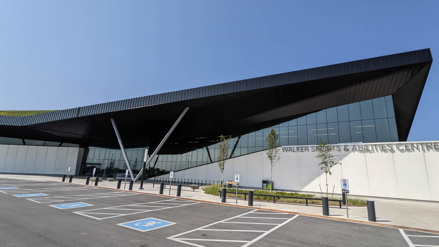 The architectural drawings initially called for CFS framing at 1800mm o.c. to support the metal deck. The spacing of the roof framing in the larger north and south soffit areas was 2500mm. Tacoma Engineers worked with the soffit supplier, CFS contractor and general contractor to maximize the deck span to span the full spacing of the OWSJ, thereby allowing the majority of the CFS sub-framing to be supported from the OWSJ without the need for intermediate sub-framing. At the other canopy areas, including edge and corner zones, the metal deck required framing at various spans, ranging from 750 mm to 2200 mm o.c. In some instances, the spacing of the roof framing did not match the spacing of the metal deck span and intermediate CFS sub-framing was required.
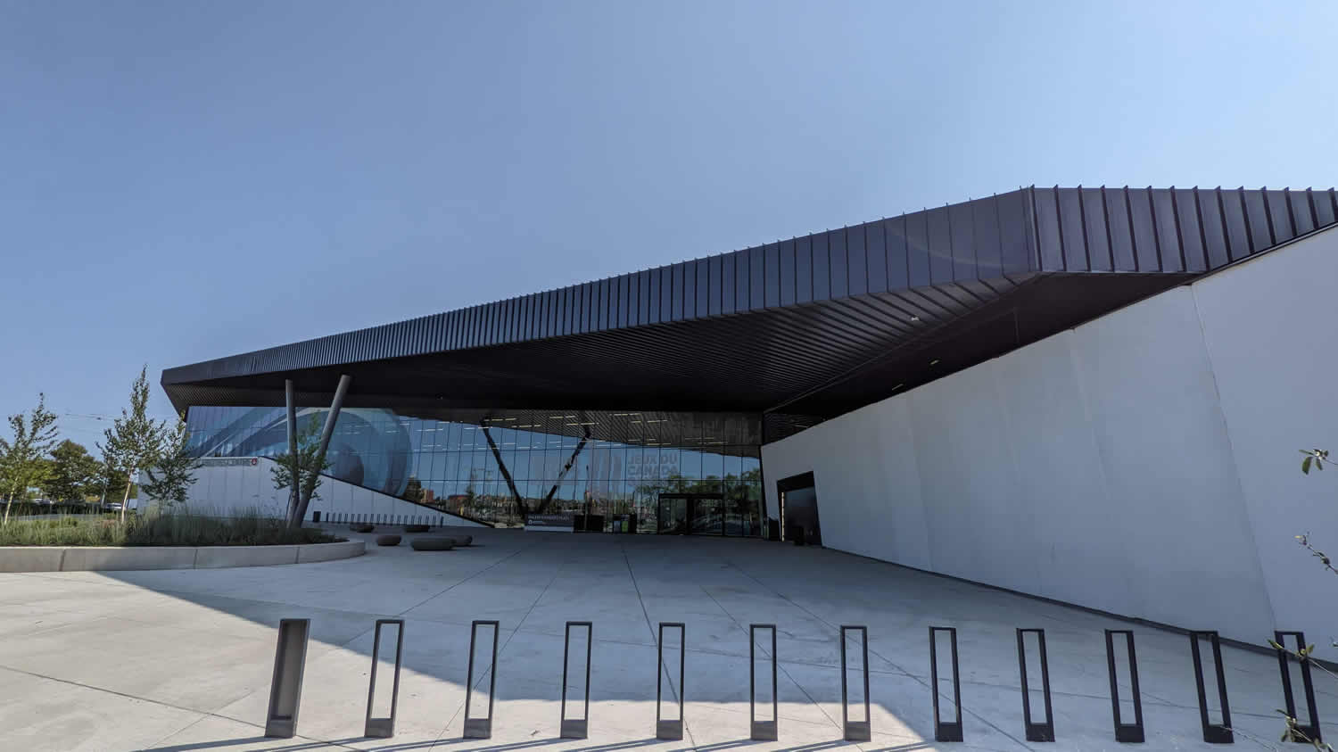 Soffits were designed for wind uplift and suction wind pressures in addition to the soffit dead loads. Lateral loads consisted of wind load on any vertical projections of the soffit assemblies and seismic loads for non-structural components. All loads were in accordance with the Ontario Building Code 2012 R2020.
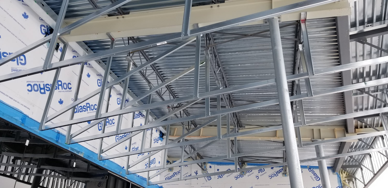
The general design consisted of providing a continuous steel stud for the metal deck support at various spacings. The continuous stud was supported by a series of hangers at 600mm – 900 mm o.c. The gauge of the continuous support stud was dictated by the metal deck supplier's fastening requirements. For the main north and south soffits, the hangers were supported from the bottom chord of the existing OWSJ along its main span. Along the edge of the soffit, where localized wind loads were higher and a smaller deck span was required, intermediate support framing was installed in between the existing roof beams.The CFS framing also had to be thermally isolated from the main building. Due to this constraint, large CFS built up beams and/or cantilevered studs were employed at the building exterior walls where there was no structural steel from which to frame.
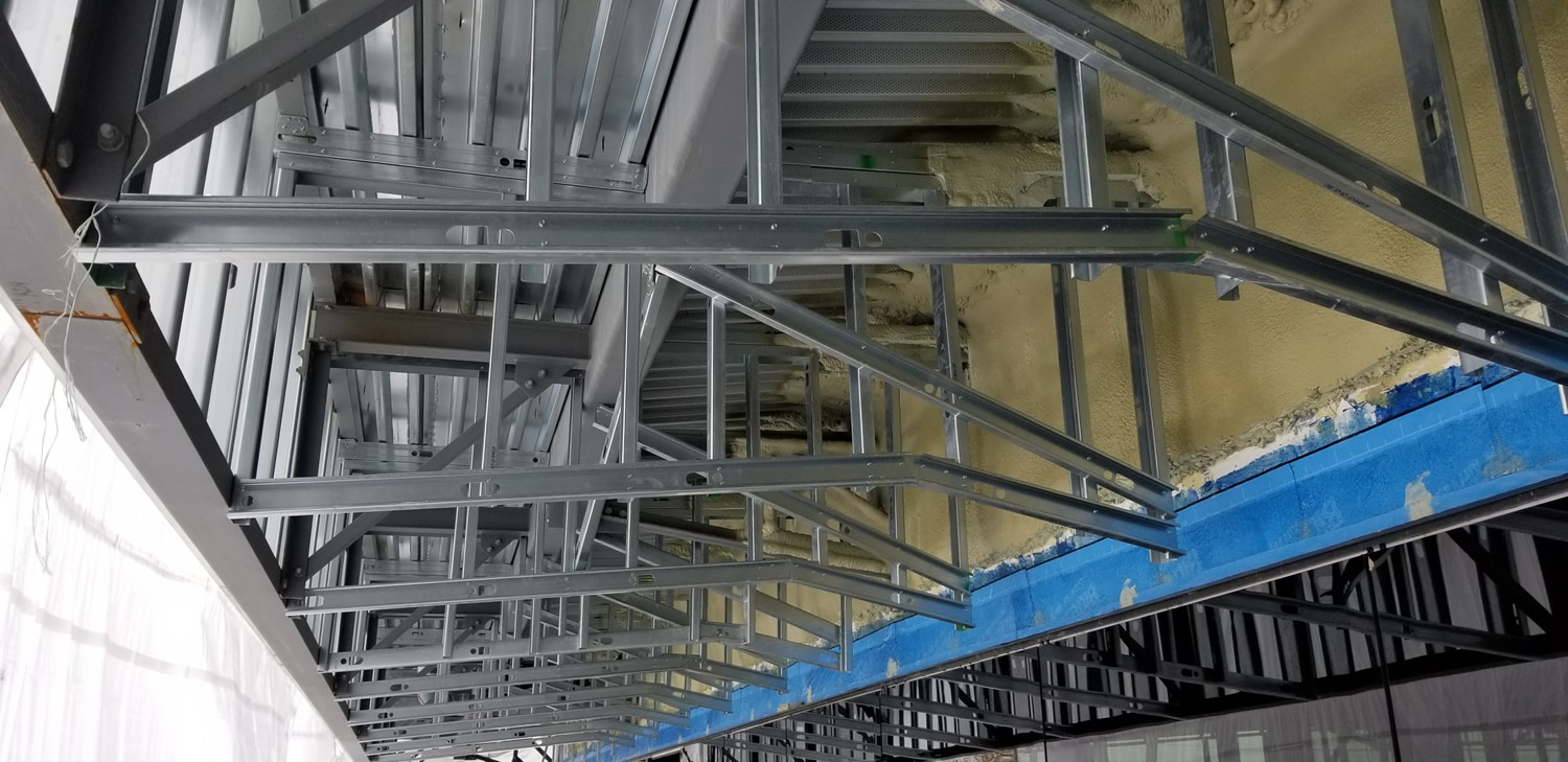
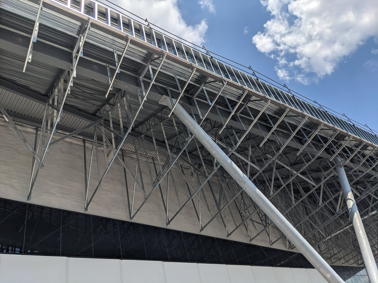 At the other canopy areas, where the roof structural steel did not line up with the metal deck spans, intermediate CFS framing was installed comprising box beams spanning between structural steel to support the hangers. At the other canopy areas, where the roof structural steel did not line up with the metal deck spans, intermediate CFS framing was installed comprising box beams spanning between structural steel to support the hangers.
Along the northwest canopy, the structural steel framing was generally perpendicular to the span of the continuous deck support. A series of box beams, both perpendicular and parallel to the deck support were required, based on the existing structural steel from which the CFS could be attached and the requirement to keep the CFS framing thermally isolated from the main building. The slope of the existing OWSJ, required break formed skewed tracks connected to the bottom chord of the OWSJ in order to allow better fit-up in the field.
In-plane and out of plane bracing were used to account for wind and seismic lateral loads. The metal deck provided diaphragm action, allowing the number of braces to be minimized and located to suit field constraints.
A total of eight field reviews were conducted to review the installed framing. Open communication with the CFS contractor was essential in order to address any field issues and provide timely remedial actions to keep the framing installation on schedule.
|