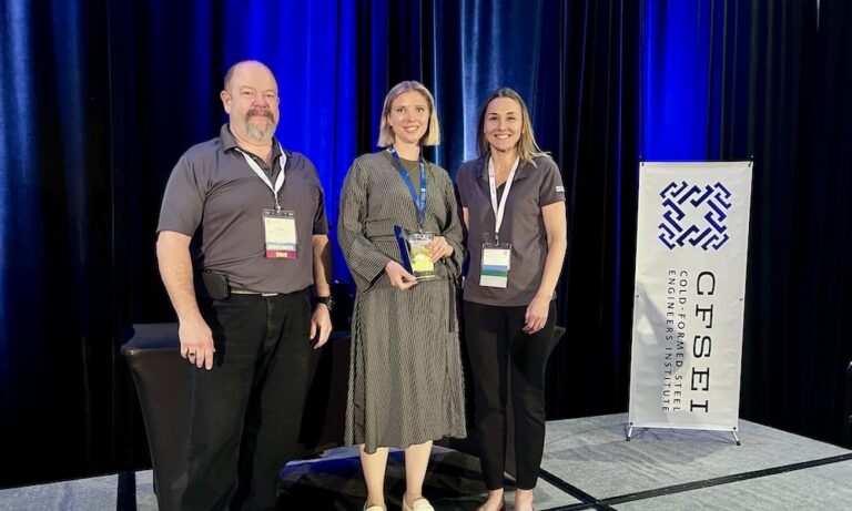
2025 CFSEI DESIGN EXCELLENCE AWARD WINNER

THIRD PLACE - COMMERCIAL
RA SMITH, INC. – LERNER RESEARCH INSTITUTE - BUILDING CBB CLEVELAND CLINIC
CLEVELAND, OHIO
 Lerner Research Institute - Building CBB Cleveland Clinic Lerner Research Institute - Building CBB Cleveland Clinic
2134 East 100th Street
Cleveland, Ohio 44106
Completion Date: 2025
Construction Cost: $2.4 Million
Owner: Cleveland Clinic Builds and Design.
Architect of Record: Hellmuth, Obata and Kassabaum, P.C. (HOK).
Engineer of Record for Structural Work: Hellmuth, Obata and Kassabaum, P.C. (HOK).
Cold-Formed Steel Specialty Engineer: Alyssa Pease, RA Smith Inc.
Cold-Formed Steel Specialty Contractor: Tom Garcea, Jr., R.G. Construction Services, Inc.
Award Entry Submitted by: Alyssa Pease, RA Smith Inc.
Project Background

Internally, raSmith refers to this project as Cleveland Clinic (CC). raSmith’s primary role was to design modular research lab "pods," which would be constructed off-site, transported by semi-truck, lifted to the second floor, placed and rolled into position.
What made the project unique was raSmith’s involvement in every aspect of the process. raSmith handled the cold-formed steel (CFS) design for the free-standing pod structures. This included in-place lifting and rolling and the design of the lifting connections.
The firm also developed solutions for moving and positioning the pods for final placement. This level of involvement required seamless communication among all parties and a willingness to approach challenges with an open mind. During the planning phase, raSmith explored numerous ideas as a team and ultimately developed a quick, cost-effective solution to move and secure the pods.
This project was such a success that the hospital approached R.G. Construction to work with raSmith to develop a modular prototype for the patient rooms at the new patient tower. They also expressed interest in pursuing more projects with raSmith using this innovative construction approach.
Design Challenges and Solutions

Section 13/CF2.3. At first glance, Section 13/CF2.3might seem straightforward, but the story behind it is a standout.
When raSmith was first contracted for this project, the firm collaborated closely with our client to figure out how to construct the interior labs off-site, transport them several blocks, lift them into the air and roll them into place. Section 13/CF2.3 represents the full journey—lifting the pods, allowing them to be rolled into position, removing the roller system and anchoring the pods securely to the slab.
The development of Section 13/CF2.3began with a critical challenge: find a rolling device that could support 10,000 pounds. Using a safety factor of 2 to account for the varied loading conditions and transportation methods, raSmith explored car jacks. However, most car jacks lacked the 360-degree rotation needed to position the pods.
Once a suitable rolling device was identified, raSmith next determined how to properly distribute the lab's weight across the device.

While considering weight distribution for rolling, raSmith also had to think about weight distribution for lifting. Ultimately, the firm decided to lift the pods in the exact location where we planned to roll them.
The 12ga posts allowed for the lifting bracket connection as well as the spreader beam connection. The firm spaced the four sets of lifting/rolling points evenly along the long sides. The spreader beams provided enough surface area to fully support the rolling device and sufficient capacity to distribute the weight of the pod effectively. The posts stabilized and supported the pods by being the shear wall posts.
This also gave the firm a heavier member for the lift bracket connection. Using 12ga material allowed for the highest capacity connection, resulting in the least amount of required lifting points. Additionally, the double 12ga (97mil) stud post allowed us to make a double clip connection at the spreader beam.
The spreader beam required two studs and clips to first transfer the load into the spreader but also have enough coverage for full bearing on the lifting device. The spreader beam also could not be lapped since it had to be removable with minimal disturbance to the already-finished interior drywall.
In summary, while Section 13/CF2.3 may appear standard initially, it represents countless hours of research, development and problem-solving. It reflects a close and trusting partnership with the client, enabling the design firm to push boundaries and deliver a solution that achieved significant cost savings. The project’s success has impressed the entire team, leading to plans for implementing a similar approach to an upcoming project.


|