2024 CFSEI CREATIVE DETAIL WINNERS

THIRD PLACE
DIGITAL BUILDING COMPONENTS LLC
MERIDIAN MEDICAL OFFICE BUILDING
SANTA FE, NEW MEXICO
 Meridian Medical Office Building Meridian Medical Office Building
4200 Beckner Road
Santa Fe, New Mexico 87507
Completion Date: 2023
Construction Cost: $100 Million
Owner: Santa Fe Las Soleras Medical Development LLC.
Architect of Record: Lisa Kincaid, Page Southerland Page, Inc.
Engineer of Record for Structural Work: Steven C. Ball, P.E., S.E., AG&E.
Cold-Formed Steel Specialty Engineer: Nick Yuen, P.E., Buehler Engineering Inc.
Cold-Formed Steel Specialty Contractor: Travis McCoy, P.E., S.E., Digital Building Components LLC; Venkata Charan, P.E., Digital Building Components LLC.
Award Entry Submitted by: Venkata Charan, P.E., Digital Building Components LLC.
Project Background
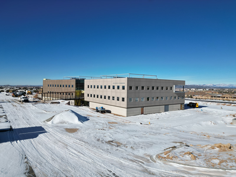
 Meridian is a multi-specialty medical office building and comprehensive cancer care center. The building houses up to 50 infusion bays, a lab and an advanced imaging facility with interventional radiology. The outpatient facility is planned to include primary care, general surgery, cardiology, pulmonary etc. Meridian is a multi-specialty medical office building and comprehensive cancer care center. The building houses up to 50 infusion bays, a lab and an advanced imaging facility with interventional radiology. The outpatient facility is planned to include primary care, general surgery, cardiology, pulmonary etc.
The building is a 95,000 sq-ft structure comprising concrete over metal deck with steel-braced frame and 30,000 sq-ft prefinished exterior cold-formed steel (CFS) non-load-bearing wall panels encompassing the structure.
Digital Building Components, based in Phoenix, was the CFS fabricator, and Buehler Engineering was the CFS specialty engineer.
Design Challenges and Solutions
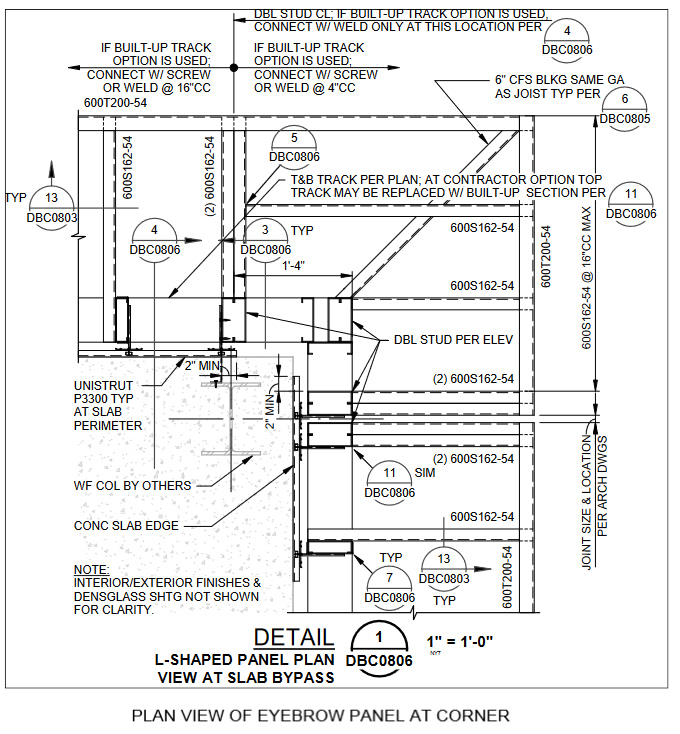
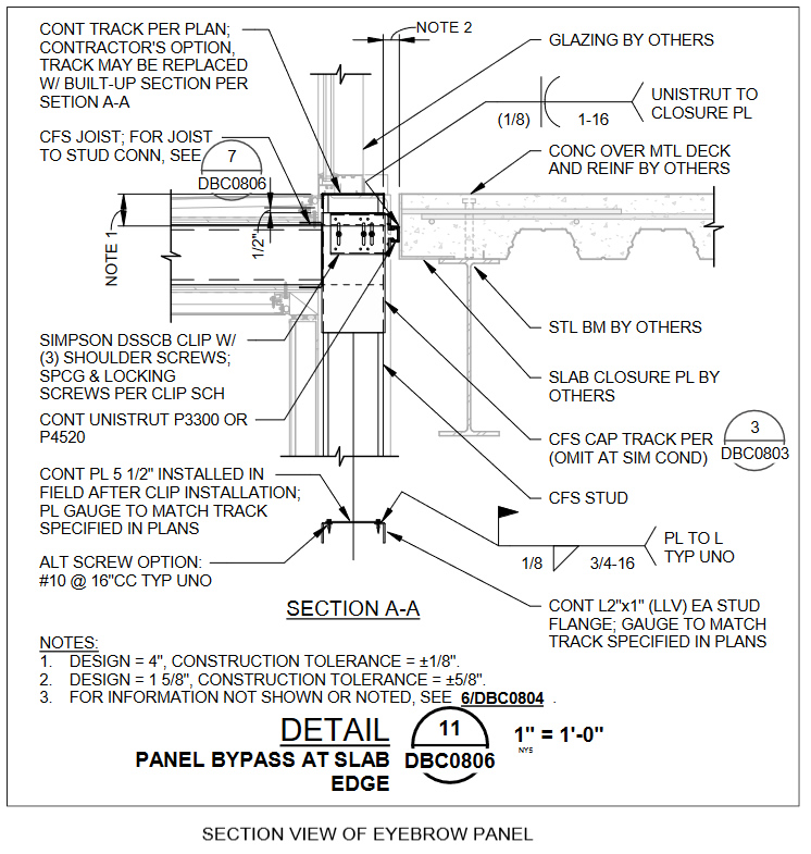
The eyebrow in the Meridian medical office building is about 60' long and cantilevers out by 2' from the exterior wall. Framing an eyebrow in the field involves time and safety of the person working on it. Digital Building Components (DBC) came up with an idea of including the eyebrow framing within its prefinished exterior non-load-bearing walls.
Issue 1. During the design coordination, the project team found that the eyebrow and wall top track would be flush with the top of the slab, which didn’t give any access to make a connection between the studs and the slab on the back. The team’s solution called for using CFS angles in the place of top track. The angles gave access to install clips in the field. Once the studs were clipped, the team could add a flat plate on top of the angles.
Issue 2. During the design phase, the eyebrow was designed and detailed to be stick framed so the force transfer could happen directly to the studs in the wall and to the clips. This involved a reduction in moment, reducing the size of the studs, and a reduction in welds on unistrut to bent plate connection. Once the team fabricated the mockup panel, they found the panel’s tolerance varied from the ¼” tolerance AISI allows for non-load-bearing CFS walls. Fabrication had to be precise, and stick-framing each stud of the eyebrow in the shop was time-consuming and created issues at the connection between the eyebrow studs and wall studs.
With the lessons learned from the mockup, the eyebrow panel was redesigned by panelizing the eyebrow and the wall panels, thereby reducing the tolerance issues. The eyebrow stud web and flanges were welded to the track from behind and connected to the wall studs with welds at the top and bottom of the track. The panelization of the eyebrow required increasing the gage of the studs, due to the slight increase in moment, but the panelization approach far outweighed the savings gained from consistent tolerance and time saved during framing.


|