2024 CFSEI CREATIVE DETAIL WINNERS

SECOND PLACE
EXCEL ENGINEERING, INC.
DNS CAPITAL
CHICAGO, ILLINOIS
 DNS Capital DNS Capital
410 North Michigan Avenue, Suite 17
Chicago, IL 60611
Completion Date: 2016
Owner: DNS Capital.
Architect of Record: Dirk Denison Architects.
Engineer of Record for Structural Work: TGRWA, LLC.
Cold-Formed Steel Specialty Engineer: Joe Wilkum, Excel Engineering, Inc.
Cold-Formed Steel Specialty Contractor: Nick Erickson, E&K of Chicago.
Award Entry Submitted by: Joe Wilkum, Excel Engineering, Inc.
Project Background
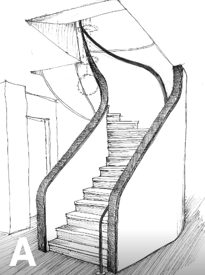 Excel Engineering was contacted by E & K of Chicago regarding the DNS Capital project located in Chicago, Illinois. E & K sent the Hand Sketch shown in Figure A. The sketch was of a curved staircase that the architect wanted constructed out of cold-formed steel (CFS) framing members. After reviewing the sketch, Excel Engineering decided that the best approach would be to simply take this one step at a time. Excel Engineering was contacted by E & K of Chicago regarding the DNS Capital project located in Chicago, Illinois. E & K sent the Hand Sketch shown in Figure A. The sketch was of a curved staircase that the architect wanted constructed out of cold-formed steel (CFS) framing members. After reviewing the sketch, Excel Engineering decided that the best approach would be to simply take this one step at a time.
Design Challenges and Solutions
Step One – Accept the Challenge. The challenge was designing a curved stair that could be easily built utilizing straight cold-formed steel members. Challenge accepted!
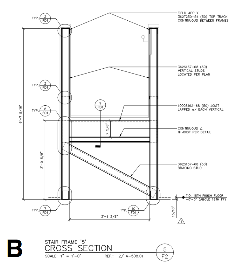
Step Two - Stability Design. Creatively frame a curved stair with straight pieces. This part seemed straightforward: Design a series of straight frames and fan them out like the spokes of a wheel. Since this would be a free-standing set of stairs, the frames needed to be stable. The Excel Engineering team designed an “H” frame for each step with a diagonal underneath to resolve the stability in the sideways direction Figure B. Excel Engineering used the sheathing to stabilize the forces in the direction up/down to the steps. The vertical portions of the “H” would resist the weight and cantilever up to form the handrails.
Step Three – Constructability. The stairs contained a total of 18 steps, each step having 4 corners. To locate one corner of a step, the Excel Engineering team took an X, a Y and a Z measurement.
18 steps x 4 corners x 3 dimensions = 216 field dimensions
The Excel Engineering team asked these questions: To build this curved staircase, wouldn’t we want to take as few field measurements as possible? Can we creatively eliminate some or all the field dimensions?
The team decided to have the drafter elevate each “H” frame step with dimensions. This way the 18 steps could be built off site. (See Figure B, which shows an example elevation for one step. Elevations were drawn for each step.)
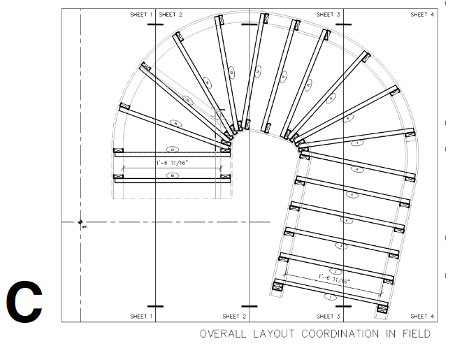
How could the Excel Engineering team eliminate the X and Y measurements? The only way they could think of eliminating these dimensions would be to print a life size floor plan, and that’s exactly what they did. Using a large-scale printer, which could print 3 feet wide by 20 feet long, the specialty engineer printed a life size floor plan indicating Step 1 through Step 18 and also printed stud profiles for all vertical portions of the “H.”
Crap! The specialty engineer designed all “H” frames with 1-5/8” flange studs. The printed plan revealed several of the vertical members of the “H” frame conflict on the plan by the tight stair corner. The only way to avoid this was to use a smaller flange – 1-3/8” flange studs solved the issue. But, the specialty engineer went back to Step Two to redesign all “H” frames using 1-3/8” flanges. Ugh!
The engineer reprinted the plan with 1-3/8” flange studs. The system fit snug with no conflicts. (See Figure C, which took four, 3’-0”-wide sheets of paper to print.)
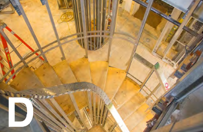
Step Four – Execution. The life-size plans were shipped to the site in a cardboard tube. The skilled E & K team laid out the life-size plan and taped it to the floor.
They stood up the vertical portion of the Step 1 “H” frame, aligned it with the Step 1 printed profile and bolted them to the floor. Then, they stood up the Step 2 “H” frame, aligned it with the Step 2 printed profiles and bolted them, and so on.
No X and Y field dimensions were taken, since all the steps were printed on the life-size plan.
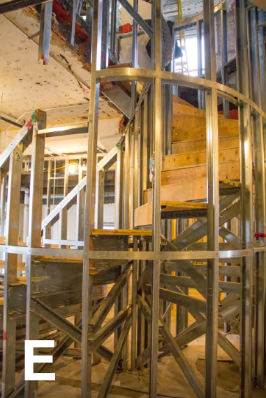
Step Five – Finished Project. E & K did an amazing job constructing this project. They are a joy to work with. (See Pictures D and E, which show the paper profiles on the floor.

|