2024 CFSEI CREATIVE DETAIL WINNERS
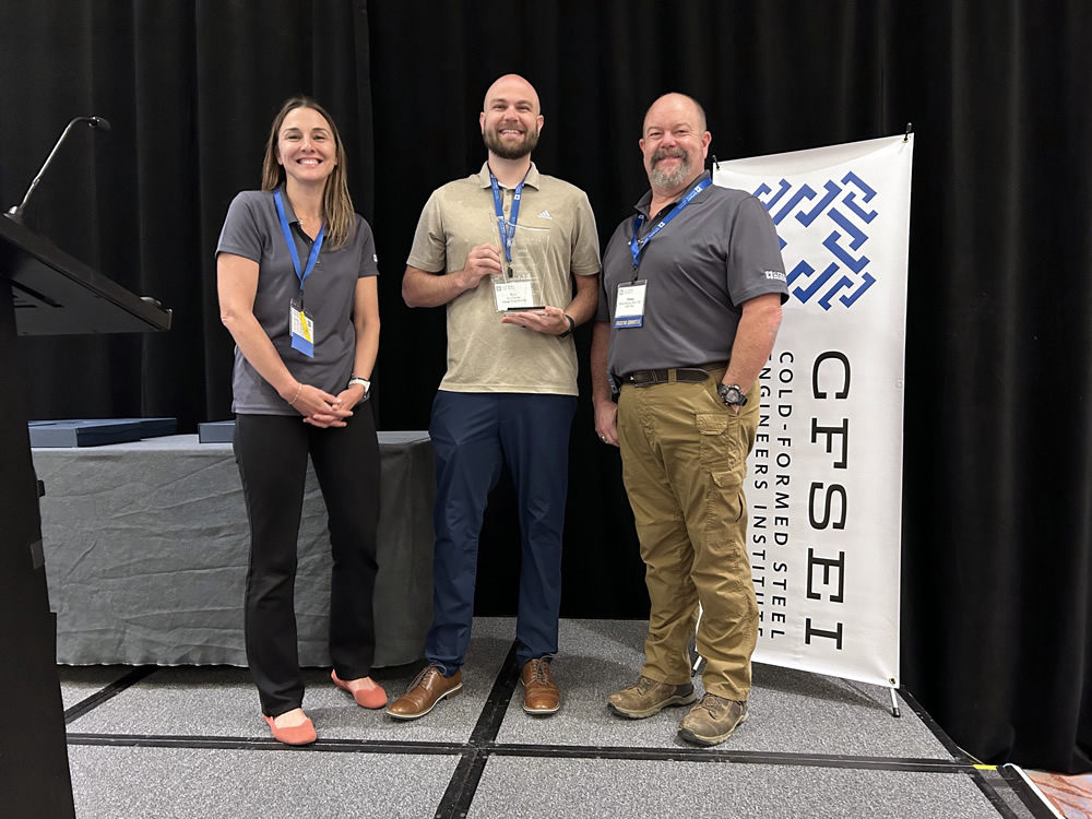
FIRST PLACE
ENSIGN ENGINEERING AND LAND SURVEYING
UNIVERSAL STUDIOS HOLLYWOOD – MARIO KART RIDE
UNIVERSAL CITY, CALIFORNIA
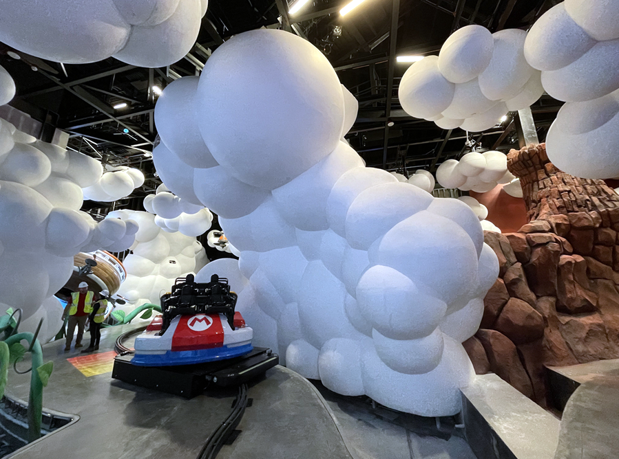 Universal Studios Hollywood – Mario Kart Ride Universal Studios Hollywood – Mario Kart Ride
100 Universal City Plaza
Universal City, CA 91608
Completion Date: January 2023
Owner: Universal Studios.
Architect of Record: Rajan Prakash Pradhan, Universal Creative.
Engineer of Record for Structural Work: Annie Fan, MSSE, P.E., AECOM.
Cold-Formed Steel Specialty Engineer: Tye M. Carlile, P.E., Ensign Engineering and Land Surveying.
Cold-Formed Steel Specialty Contractor: Shane Hastain, P.E., KHS&S.
Award Entry Submitted by: Scott B. Roche, P.E., S.E., Ensign Engineering and Land Surveying.
Project Background
 In early 2023, Universal Studios Hollywood introduced SUPER NINTENDO WORLD to its park, featuring the notable addition of the Mario KartTM: Bowser’s Challenge ride. This attraction immerses visitors in various scenes inspired by the popular game Mario KartTM. Notably, one of these scenes simulates a thrilling race through clouds. Ensign Engineering and Land Surveying, Inc. collaborated closely with Universal Creative, AECOM and KPFF to engineer the expansive clouds, which were constructed using cold-formed steel (CFS) stud framing and coated with a thin layer of plaster. In early 2023, Universal Studios Hollywood introduced SUPER NINTENDO WORLD to its park, featuring the notable addition of the Mario KartTM: Bowser’s Challenge ride. This attraction immerses visitors in various scenes inspired by the popular game Mario KartTM. Notably, one of these scenes simulates a thrilling race through clouds. Ensign Engineering and Land Surveying, Inc. collaborated closely with Universal Creative, AECOM and KPFF to engineer the expansive clouds, which were constructed using cold-formed steel (CFS) stud framing and coated with a thin layer of plaster.
Design Challenges and Solutions
Ensign Engineering and Land Surveying’s goal was to create eye-catching cloud shapes, though the curved and organic cloud shapes posed structural design challenges.
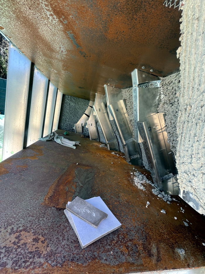 The firm’s first attempt to capture this shape was to put together curved cold-formed steel (CFS) steel studs to shape the clouds. This proved difficult for accurate structural analysis due to the significant section removal needed to create the curved Shapes, as seen in Figure 1. The firm’s first attempt to capture this shape was to put together curved cold-formed steel (CFS) steel studs to shape the clouds. This proved difficult for accurate structural analysis due to the significant section removal needed to create the curved Shapes, as seen in Figure 1.
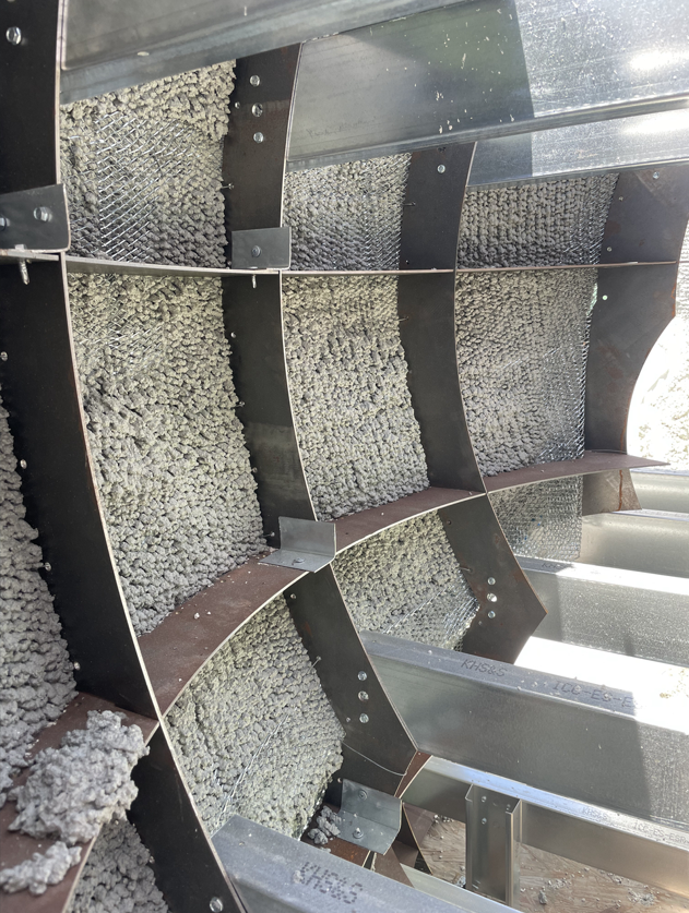
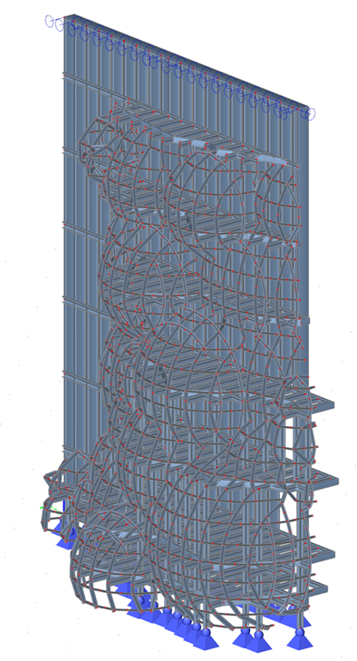
After brainstorming solutions, the team developed an innovative approach: CNC-cutting steel plates precisely to the 3D model cloud contours. The first mock-up of this is shown in Figure 2. This mockup allowed an exact match to the desired aesthetic shapes and enabled easier and more accurate analysis using our 3D modeling software, SCIA. (See Figure 5 for an isometric view of one of the first clouds designed using this technique in SCIA.) Figure 2 shows the ribs that create the various cloud "bubbles", the CFS stud platforms and the CFS stud support wall behind it.
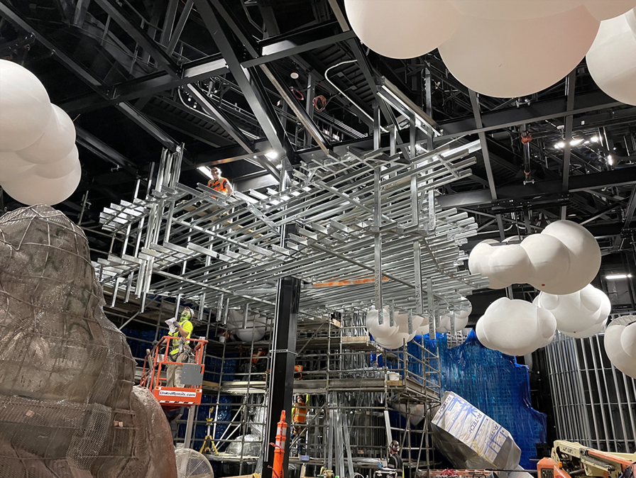
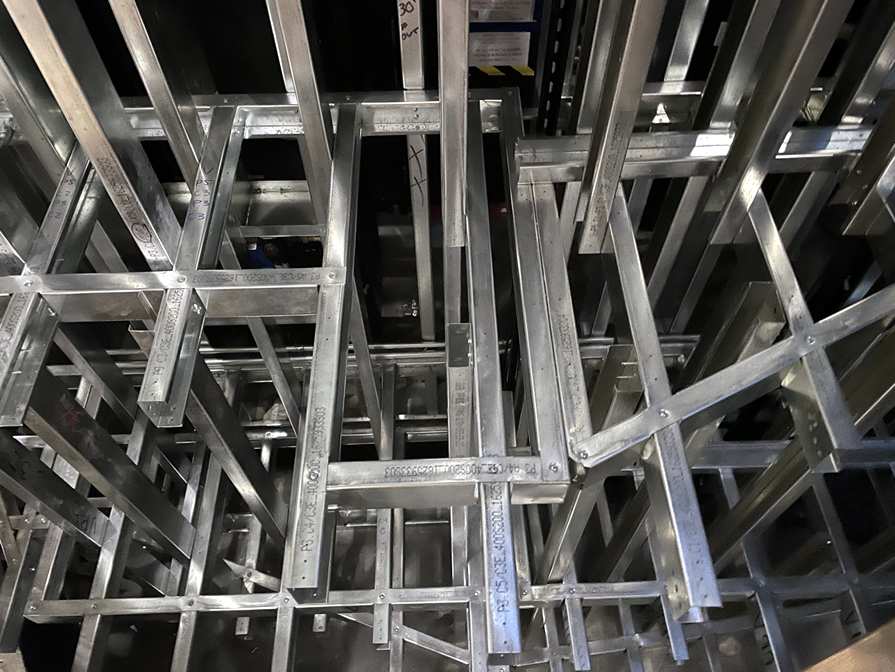
The initial plates and cantilevered stud platforms alone lacked adequate rigidity, so the Ensign Engineering and Land Surveying team added steel stud blocking within the platforms for reinforcement. Figure 3 provides a top-down perspective of one of the platforms before the CNC "ribs" were incorporated to define the cloud shapes. The combination of CNC-cut plates acting as "ribs" and the blocking studs enabled the forms to be both structural and sculptural.
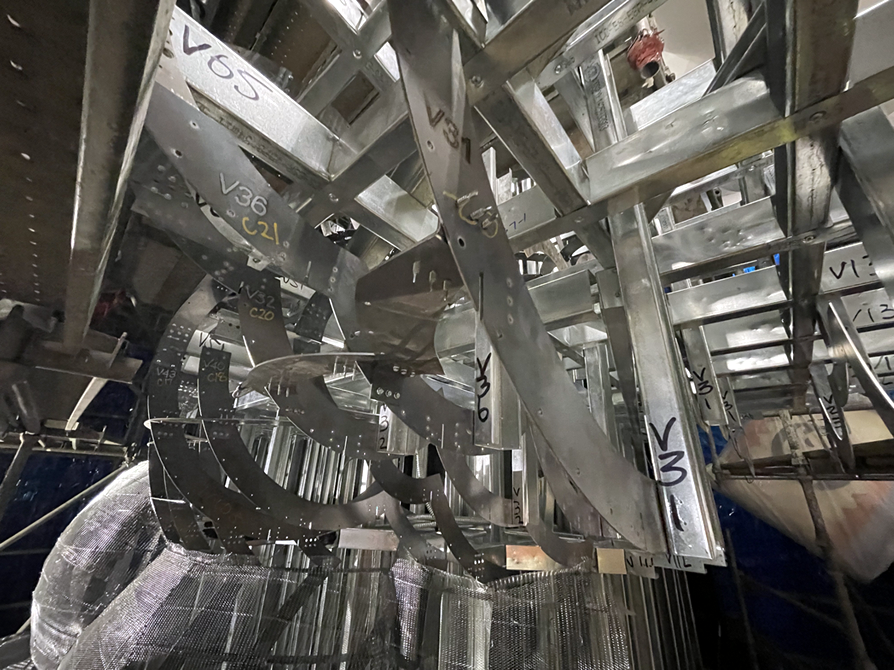
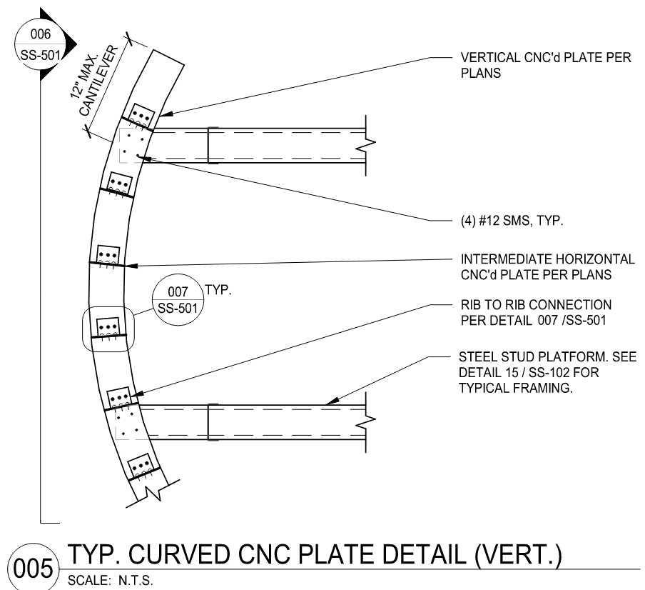
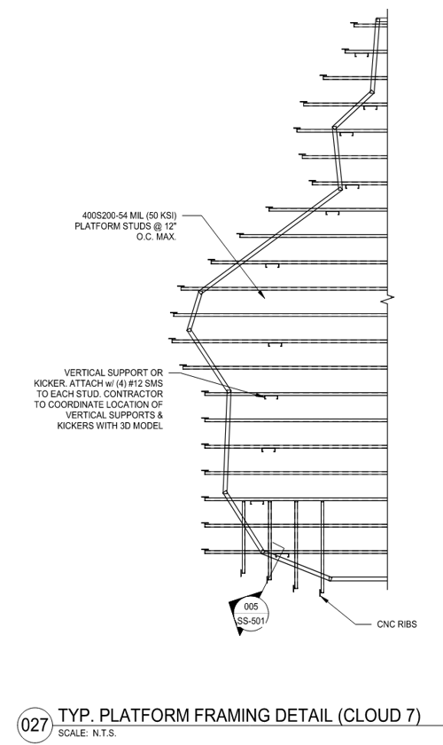
Fabricating the ribs and platforms was an intricate process done in coordination with KHS&S and Stud.IO. Using the 3D model, Ensign Engineering and Land Surveying designed connections and openings to allow for stud placement (Figures 6 and 7). Stud.IO then prepared the programming to be used by a Howick machine to roll and cut the steel studs to specific lengths.
 A Howick machine, for those unaware, is a machine that produces the metal framing pieces required for a project based on a framing package produced in CAD. This machine not only rolled and cut studs to exact specifications but also incorporated slots and dimples to facilitate ease of construction. A Howick machine, for those unaware, is a machine that produces the metal framing pieces required for a project based on a framing package produced in CAD. This machine not only rolled and cut studs to exact specifications but also incorporated slots and dimples to facilitate ease of construction.
This collaborative process allowed construction of stunning yet functional platforms that captured the essence of clouds (Figure 4). Solving the technical challenges required extensive teamwork, engineering creativity and pushing fabrication boundaries. The result is a visually striking sculptural statement delivered through innovative solutions.
While shaping the clouds was difficult, supporting the massive central cloud (C7 as we named it) presented an even greater structural puzzle. With minimal direct load path to foundations, we had to get creative. After multiple discussions with the design teams, we devised a plan to hang the upper portion from steel above, while ground-supporting the lower section.
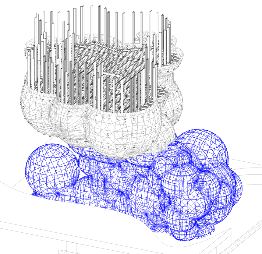
Figure 8 shows an isometric view of cloud 7 from our drawings. The bottom, ground-supported half is highlighted in blue while the upper half that is hung from the ceiling above is shown in white. The figure shows portions of the internal platforms and drop studs used to hang the structure from above.
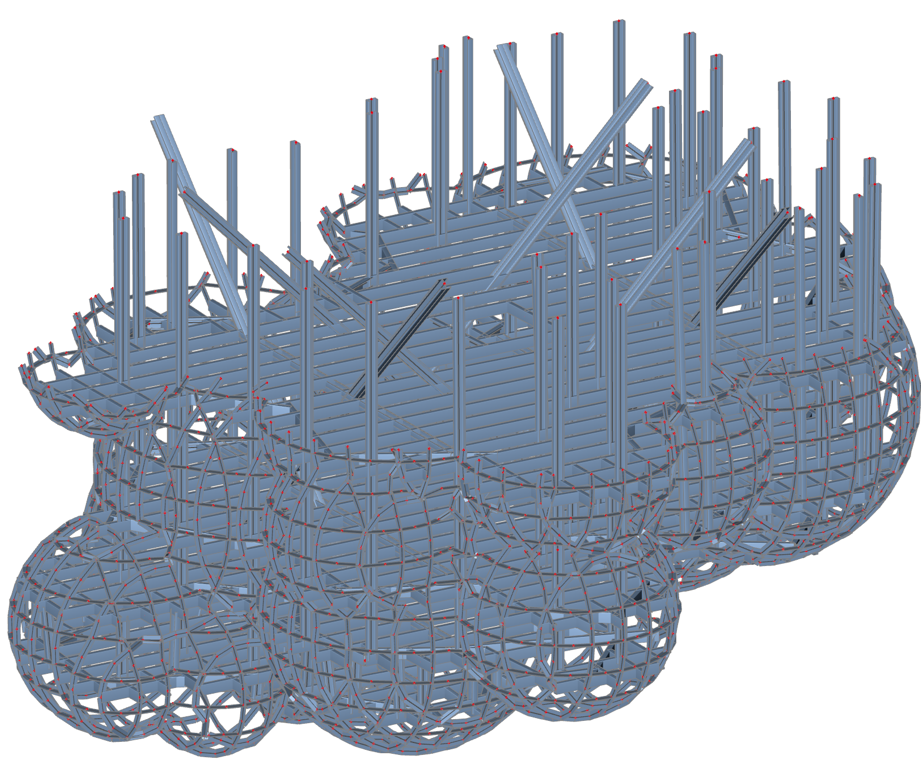
The intricate upper cloud was essentially an elaborate hanging ceiling. Ensign Engineering and Land Surveying suspended it from vertical steel studs anchored above. To meet seismic requirements, the team installed internal lateral bracing in both directions. See Figure 9 for an isometric view of our 3D model in SCIA for the upper portion of this cloud.
 This innovative approach enabled constructing the breathtaking form of Cloud C7 without compromising structural integrity. The stunning result doesn't truly capture the engineering complexity behind it. Figure 10 shows the upper half of the cloud being constructed, while Figure 11 shows the cloud getting some finishing touches before opening. Overcoming the challenge of supporting this massive cloud pushed our team to devise an ingenious gravity-defying design. This innovative approach enabled constructing the breathtaking form of Cloud C7 without compromising structural integrity. The stunning result doesn't truly capture the engineering complexity behind it. Figure 10 shows the upper half of the cloud being constructed, while Figure 11 shows the cloud getting some finishing touches before opening. Overcoming the challenge of supporting this massive cloud pushed our team to devise an ingenious gravity-defying design.
Cloud C7 exemplified the monumental obstacles we cleared through a collaborative effort of creative thinking, technical expertise and perseverance. The Ensign Engineering and Land Surveying team’s sculptural statement pieces are a testament to engineering both art and structural stability in tandem.
|