2021 CFSEI DESIGN EXCELLENCE AWARD WINNERS
THIRD PLACE – MUNICIPAL
CLARKDIETRICH ENGINEERING SERVICES LLC – WILL COUNTY COURTHOUSE
JOLIET, ILLINOIS
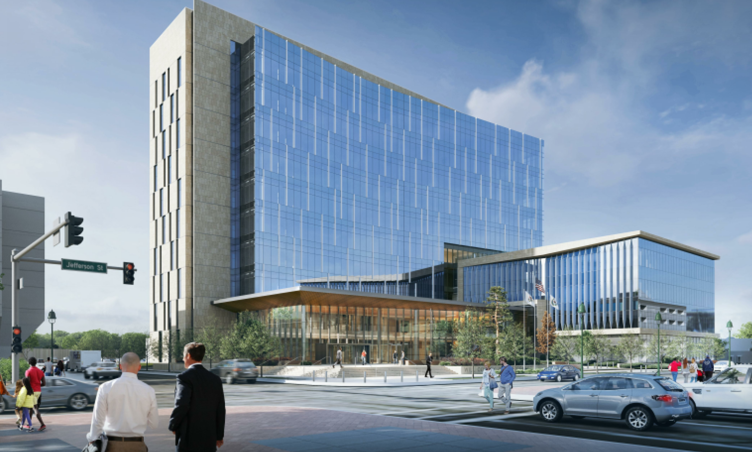
Will County Courthouse
50 West Jefferson Street
Joliet, Illinois
Completed: October 2020
Construction Cost: $215 Million
Owner: The County of Will
Architect of Record: Justin Illg, Wight & Company
Engineer of Record for Structural Work: Wight & Company
General Contractor: Gilbane Building Company
Cold-Formed Steel Specialty Engineer: Michael Holmquist, ClarkDietrich Engineering Services LLC
Cold-Formed Steel Specialty Contractor: Eli Gonzalez, DBM Services, Inc.
Award Entry Submitted by: Michael Holmquist, ClarkDietrich Engineering Services LLC
Project Background
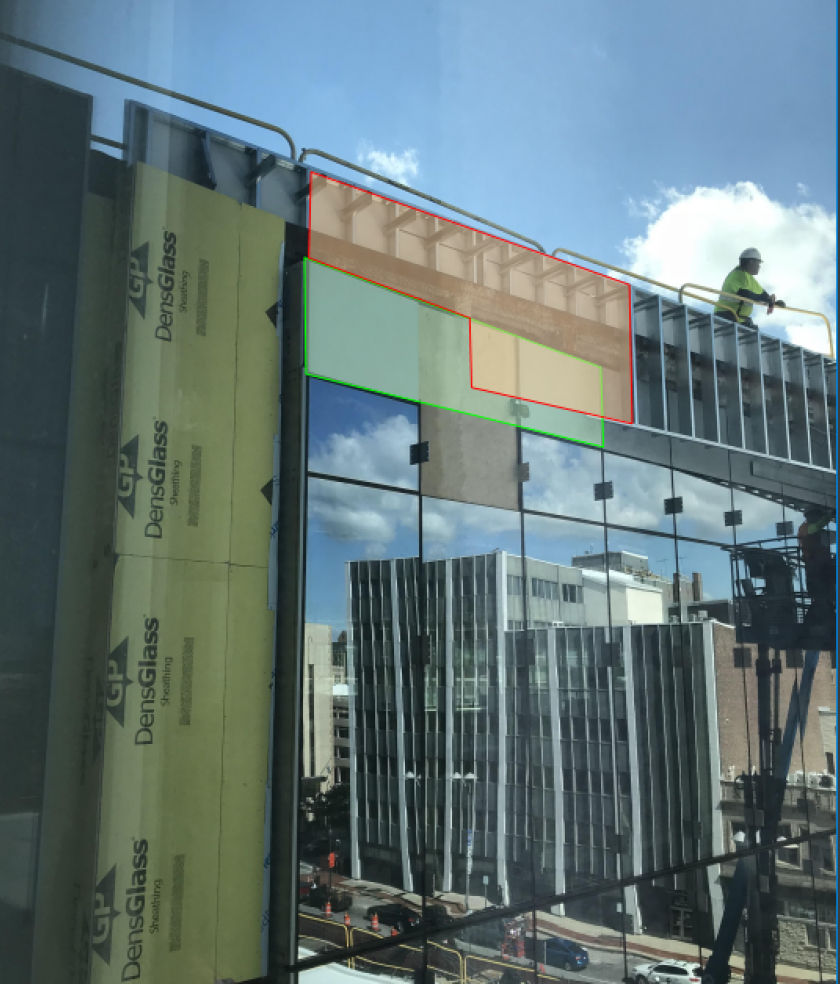
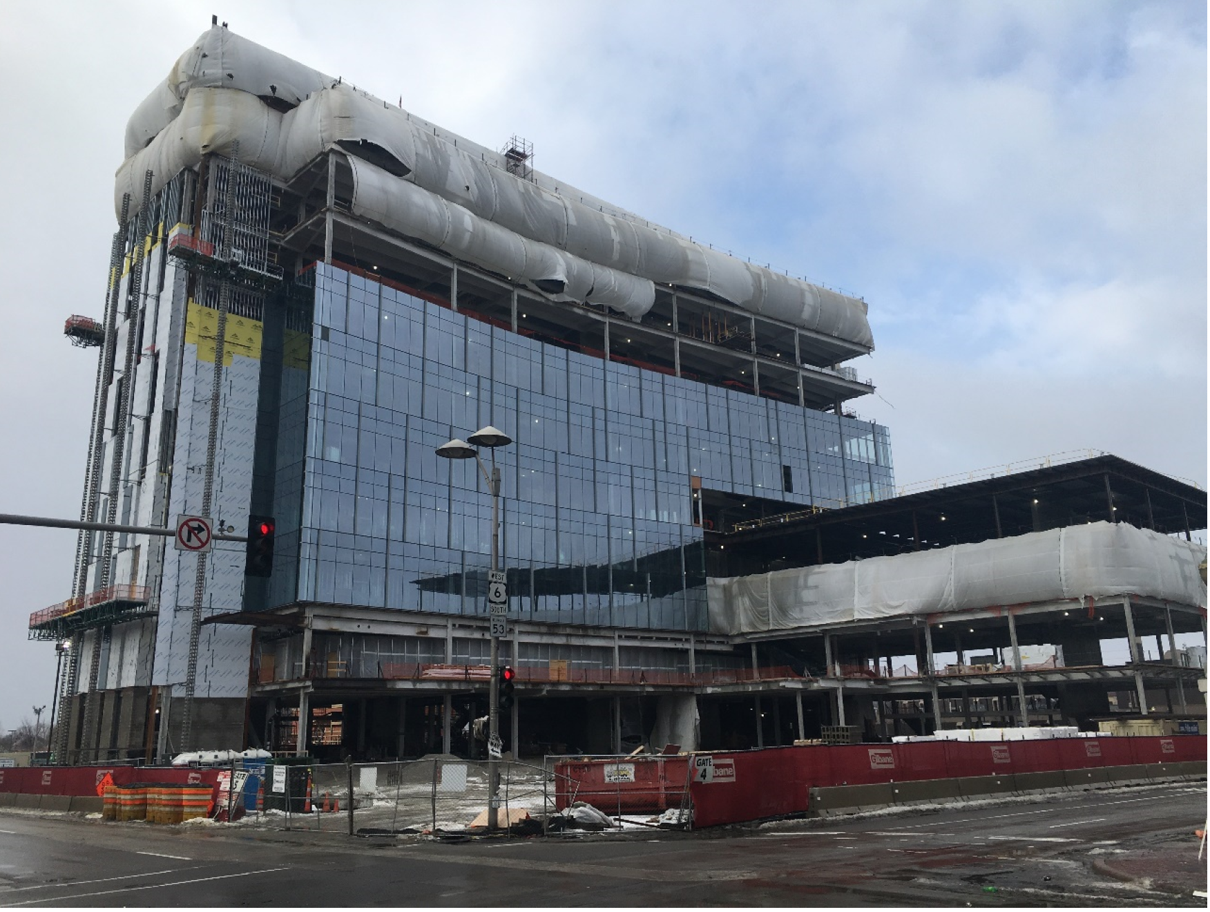
The Will County Courthouse in Joliet, Illinois, is a $215 million, 10-story renovation project consisting primarily of exterior non-axial load-bearing curtain wall framing. A three-year long construction effort, the courthouse opening was celebrated with a ribbon-cutting ceremony in October 2020.
Design Challenges and Solutions
As with most large structures, there are usually multiple items to consider, and this project was no exception. Some of the most notable challenges included:
- Coordination on the exterior façade finish system (stone rainscreen system). A relatively heavy finish with an offset from the wall studs created additional moment considerations on the stud framing, which required further engineering analysis. The framing and rainscreen sub girt system (not by CDES) required careful coordination among the respective trades in the form of various conference calls and peer reviews of the respective documents.
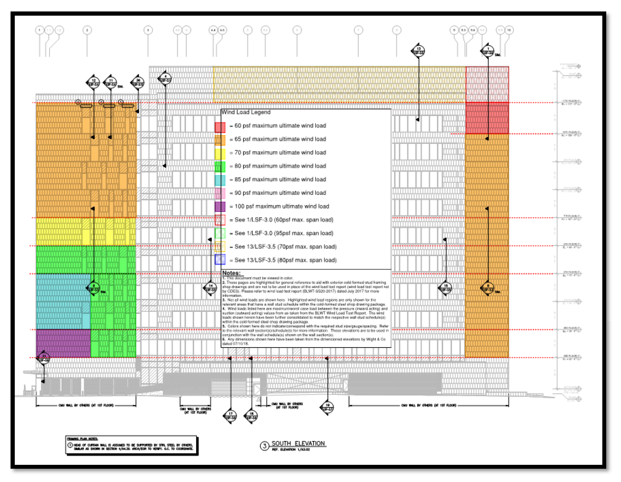
- Coordination on the wind tunnel test report. This project had a wind load study that needed to be incorporated within the cold-formed steel stud design. As with most wind load reports, there were a range of wind loads (pressures and suctions) throughout the extent of the structure. To help facilitate the stud takeoff/installation for the carpenter, CDES generated a color-coded reference document, noting the various wall schedules on the cold-formed steel shop drawings. This additional document cross-referenced the cold-formed steel shop drawings, wind load study (by BLWT), and dimensioned plans (by Wight & Co). While the typical stud design was based on ASD methodologies, the wind loads listed on the color-coded reference document were ultimate wind loads for ease of matching up with the wind load report.
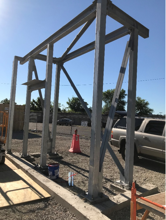
- Mock-up shop drawing submittals were also required for this project. Unfortunately, some of the information included in the mock-up was not indicative of the actual structure, and thus required some additional framing/coordination to ensure the cold-formed elements of the mock-up were still structurally sound (i.e., completed load path).
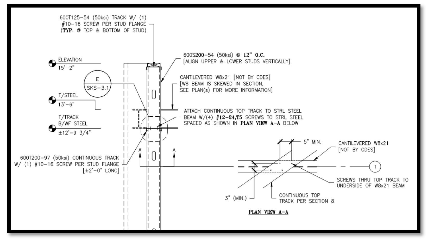
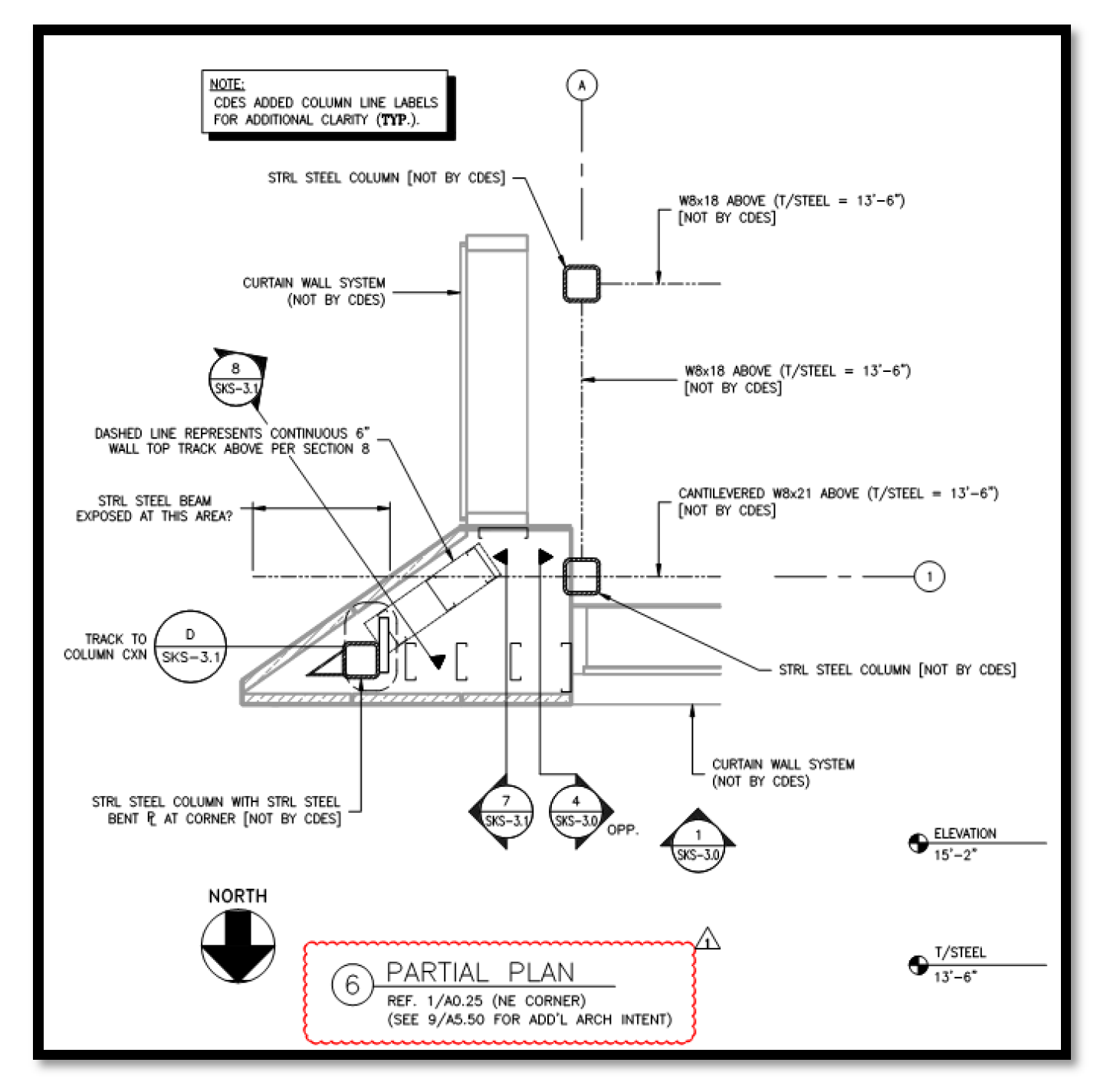
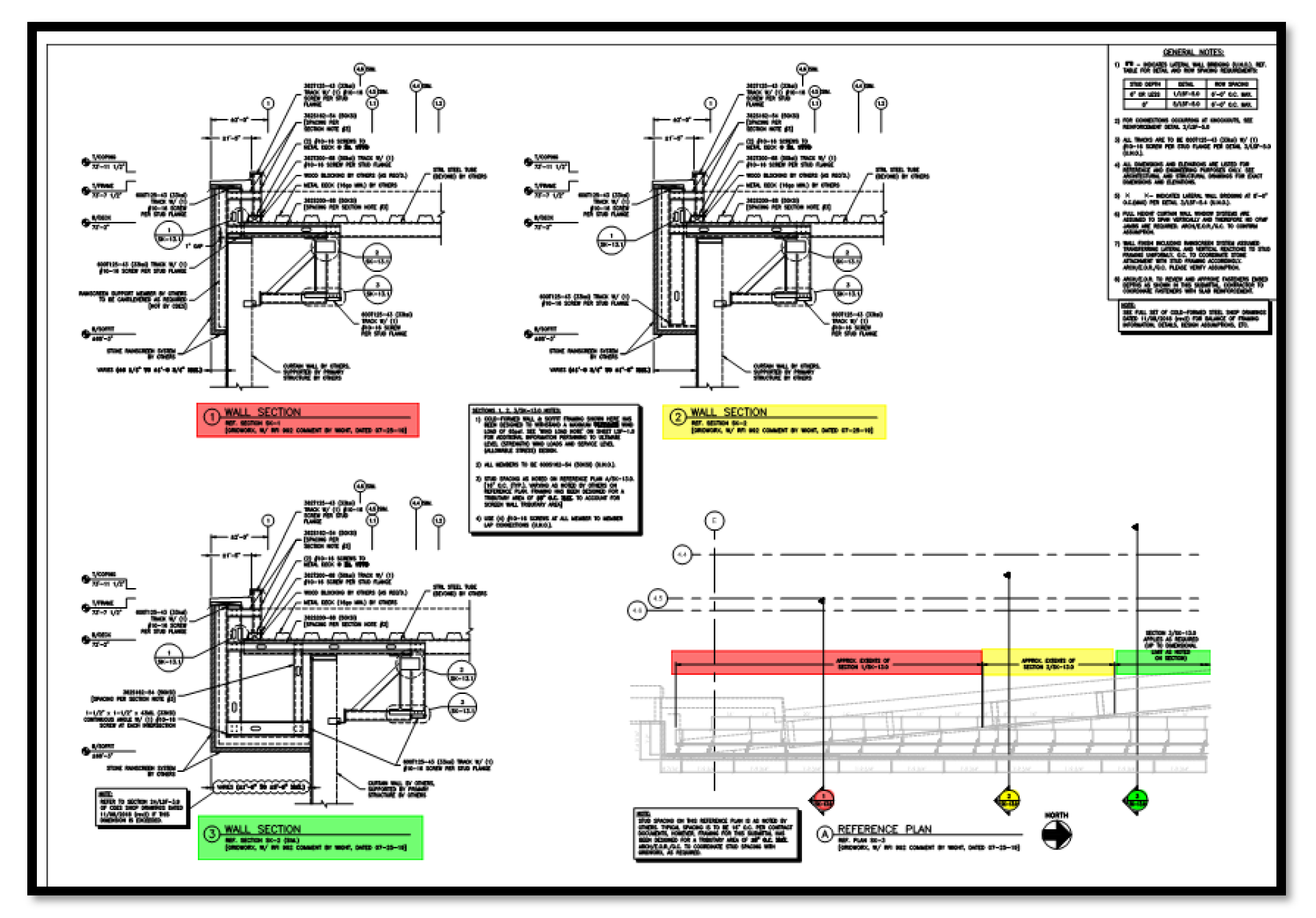
Some areas with the framing/curtain wall systems were skewed as related to the primary structure. This resulted in additional coordination needed among all the respective trades as well as specific details, requiring multiple sections, and plans illustrating the extents of each section (ref. 28/LSF-3.10 and SK-13.0 & SK-13.1). This area had two separate and alternating sections to independently support an infill stud and a hanging fascia that were at a slight skew to one another at a roof line, separated by a horizontal expansion joint to account for vertical deflection. While some of these conditions were not readily apparent on the contract documents, fortunately all parties were able to work together quickly and cohesively to understand the conditions that arose and devise timely solutions.
|