2021 CFSEI DESIGN EXCELLENCE AWARD WINNERS
SECOND PLACE – RESIDENTIAL/HOSPITALITY
McCLURE – THE DEACON
CINCINNATI, OHIO

The Deacon
424 Straight Street
Cincinnati, Ohio 45219
Completed: Early 2019
Construction Cost: $85 Million
Owner: Trinitas
Architect of Record: Heather Gleason, BKV Group
Engineer of Record for Structural Work: Lionel Dayton, BKV Group
Cold-Formed Steel Specialty Engineer: Cody Dailey, McClure
Cold-Formed Steel Specialty Contractor: Tim Eagen, Eisen Group
Award Entry Submitted by: Lauren Gutknecht, McClure
Project Background

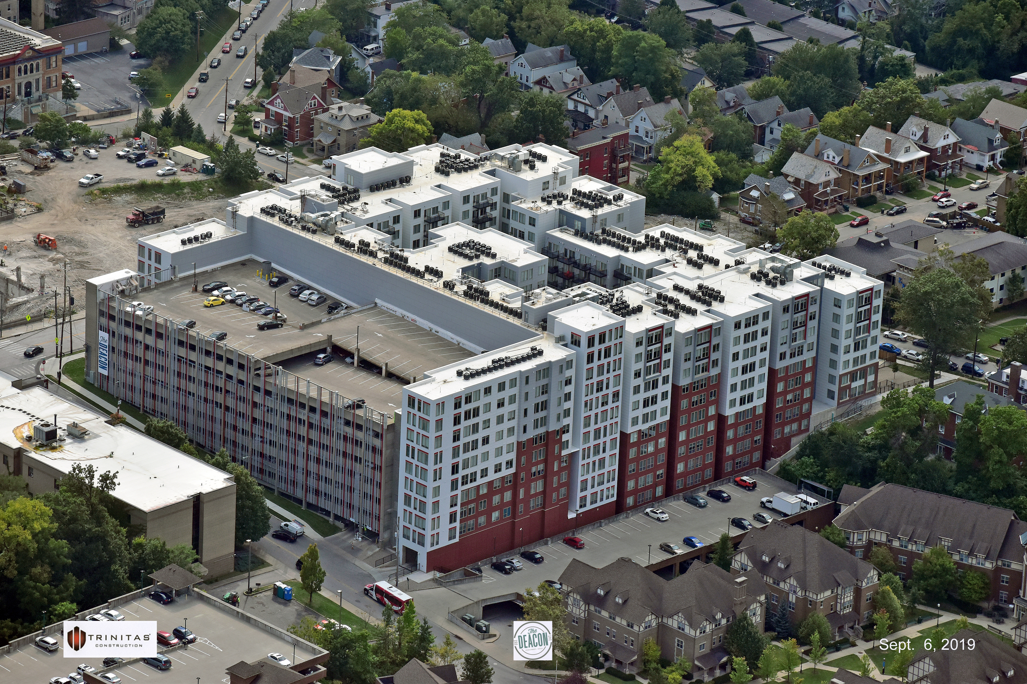
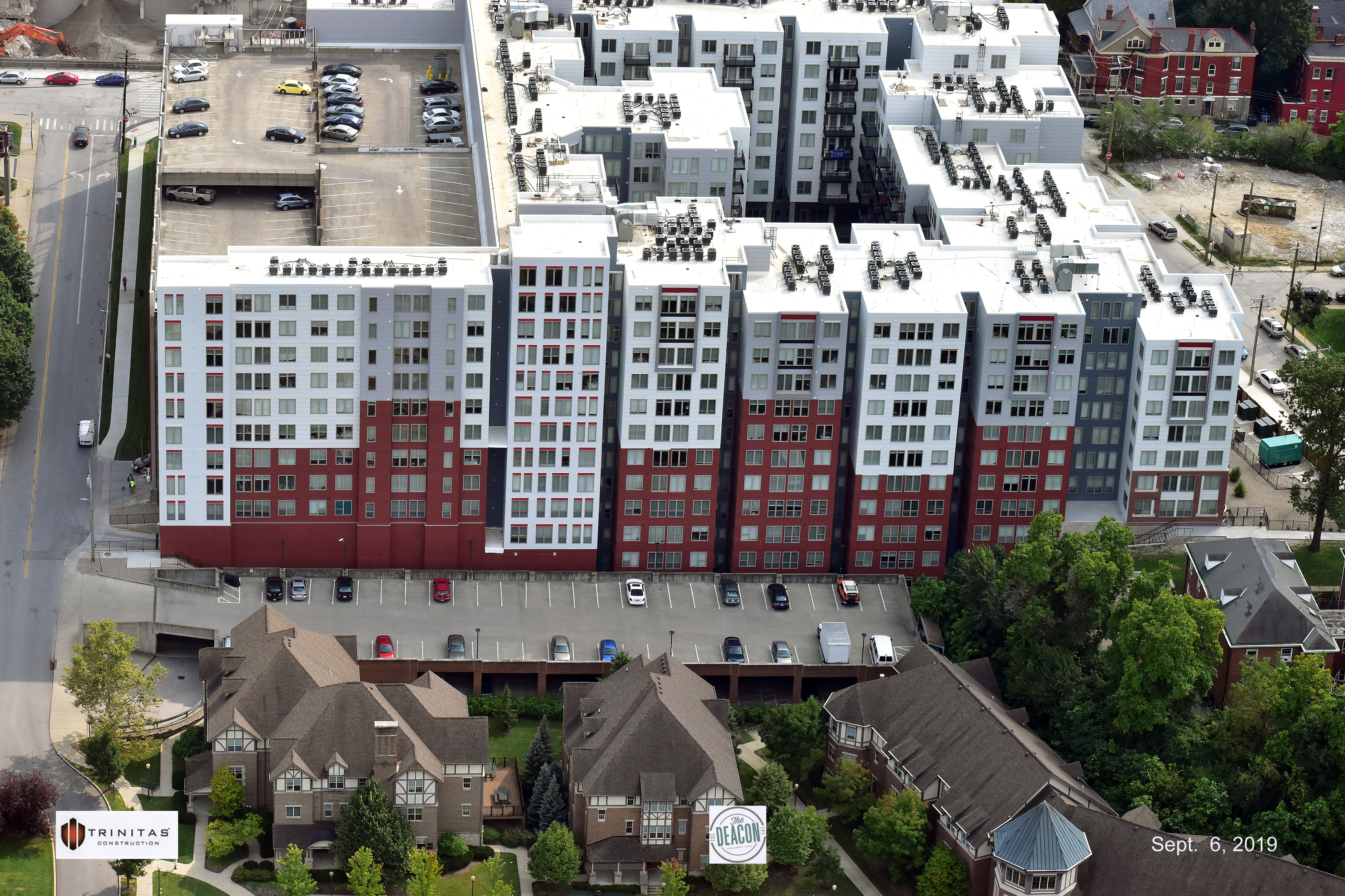
The Deacon is a 12-story collegiate housing project serving the University of Cincinnati. The sloped site required a multi-level concrete podium which is topped with load-bearing cold-formed steel (CFS) framing varying from six stories to twelve.
At nearly half a million square feet, The Deacon features over 1,000 beds, a courtyard pool, and 18,000 square feet of amenities. With no single level being identical, students can choose from studio apartments to two-story, four-bed penthouses with an impressive view of campus.
Design Challenges and Solutions

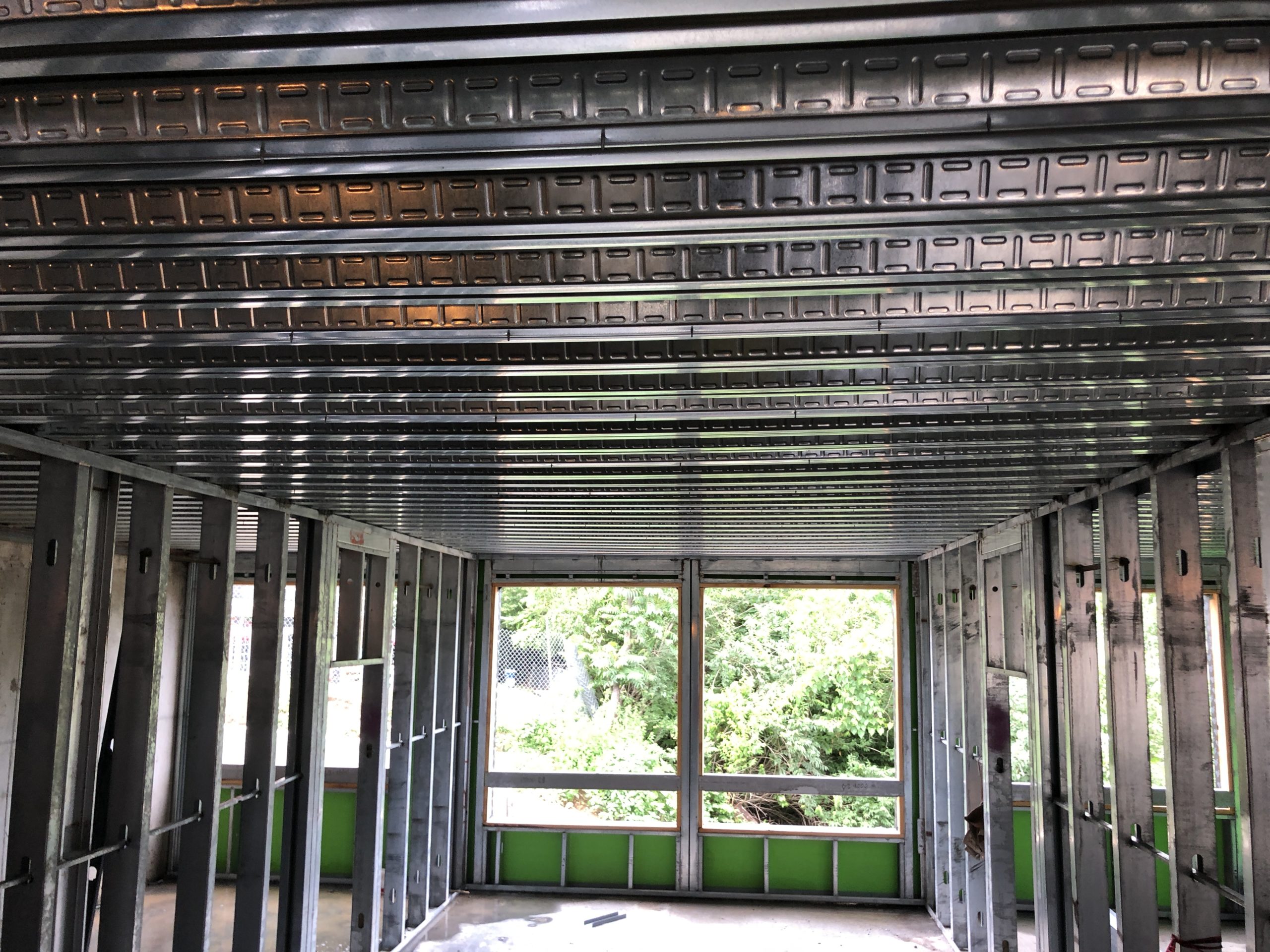
While the amenity levels are CIP concrete, all living space is framed with composite deck bearing on CFS demising walls. Framing lines were kept continuous across corridors to allow the decking to be installed in large, continuous runs, with as few direction changes as possible. McClure set the deck start dimensions before either the CFS or deck shops were started. This allowed McClure to show the exact location of all the deck flutes in plan and ensured the CFS studs would stack top to bottom on a low deck flute and not require field grouting the flute void or a load distribution member. Although this would typically be done by the deck supplier, doing so earlier in the project accelerated coordination between the structural and MEP trades.
The somewhat limited span of composite deck had the benefit of minimizing the loading on the walls and allowed for the use of single wall studs on even the 12-story portions of the building. As a result, the space between structural members was maximized for use by other trades, and fewer clashes occurred in the field.
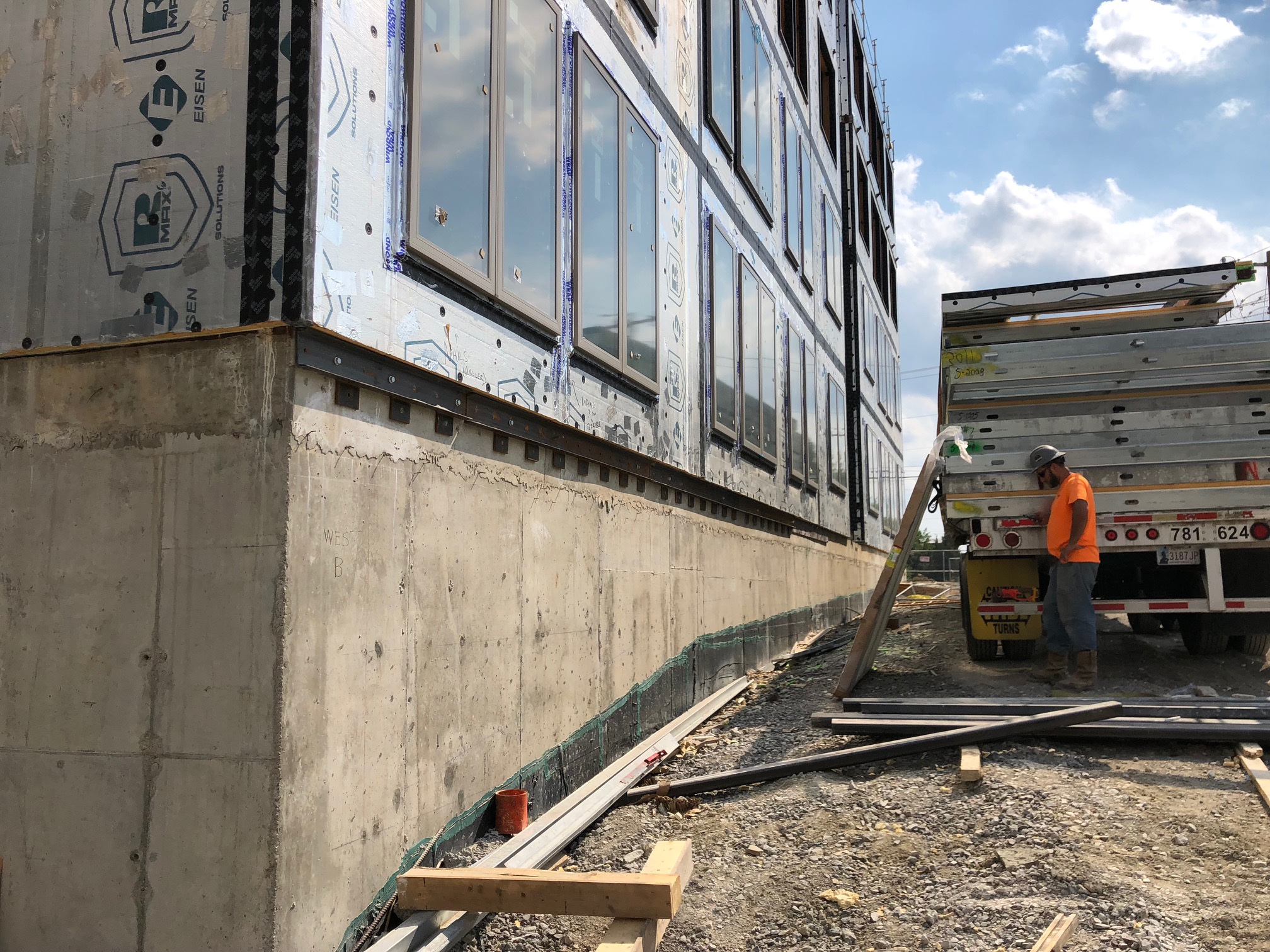
A few exterior load-bearing elevations had non-stacking randomly placed windows. Rather than carry discrete jambs down 10+ stories, a full steel model with every stud, jamb, and header was created with HSS tubes at the floor lines serving as load distribution members. The effort paid off and was considerably more economical than cascading point loads down each floor and upsizing header and jamb framing.
In years past, this structure would have been built with post-tensioned cast-in-place concrete construction. The opportunity to utilize cold-formed steel has helped push CFS to new market share, heights, innovation and possibilities. Staggered windows, bolt-on aluminum balconies, and large recesses in the building give it a unique look and help it stand out.

The gravity design of this building was no simple task, but the lateral design was equally complex. The building features two lateral force-resisting systems: one for the upper six levels, and another for the lower six levels. There are four concrete cores in the building, one in each of the four quadrants. However, since the CIP construction does not extend above Level 6 (and often stops many floors lower), it made sense to utilize CFS shear walls on the top half of the structure. To facilitate this change in lateral systems, McClure designed the Level 6 deck to act as a transfer slab to transition from four concrete cores to 58 individual strap-braced shear walls. This level was eight inches of concrete over heavy composite deck and was heavily reinforced so that all lateral loads from the six stories of cold-formed shear walls could be carried to the concrete cores.
The cold-formed shear walls themselves were non-typical due to the height of the building and seismic story forces. In certain locations toward the bottom of the CFS wall system, the top and bottom tracks had to be reinforced with steel plates to carry the horizontal component force. Floor-to-floor connections were accomplished with boundary elements that were capped with steel plates at finish floor elevation. All connections were field- or shop-welded.
In the end, this collegiate housing project pushed cold-formed framing to new heights. The Deacon has helped blaze a trail for converting mid-rise projects planned for post-tensioned or steel-framed construction to cold-formed construction.
|