2023 CFSEI DESIGN EXCELLENCE AWARD WINNERS
SECOND PLACE
MCCLURE – TITLETOWN MULTI-FAMILY RESIDENTIAL
ASHWAUBENON, WISCONSIN
 Titletown Multi-Family Residential Titletown Multi-Family Residential
1170 Brookwood Drive
Ashwaubenon, WI 54304
Completion Date: 2022
Owner: Sterling Project Development/Kaufman Development
Architect of Record: Mike Domek, AIA, LEED AP, NBBJ
Engineer of Record for Structural Work: Jeffrey Derra, P.E., S.E., LEED AP, R.A. Smith, Inc.
Cold-Formed Steel Specialty Engineer: Jesse Barnes, P.E., McClure
Cold-Formed Steel Specialty Contractor: Travis Goddard, Eisen Group and Don Guskey, Denk and Roche
Award Entry Submitted by: Lauren Gutknecht, McClure
Project Background
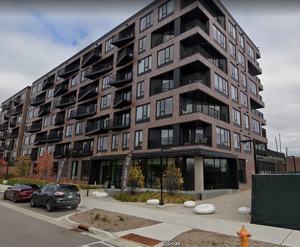
 The Titletown multi-family residential building is located in the heart of the Green Bay, Wisconsin area. As the name of the building implies, it is associated with the Green Bay Packers local commercial area known for the historically successful National Football League team. The view of Lambeau Field is uninterrupted when peering from the east side of the new structure. The overall project consists of a six-story cold-formed steel (CFS) building above a single-story podium. The typical floor construction is gypcrete over CFS open web joists spanning from demising wall to demising wall. The structural lateral system on the project is CFS strap-braced shear walls and the building exterior consists of balconies that stagger in 32-ft. bays up the building. The Titletown multi-family residential building is located in the heart of the Green Bay, Wisconsin area. As the name of the building implies, it is associated with the Green Bay Packers local commercial area known for the historically successful National Football League team. The view of Lambeau Field is uninterrupted when peering from the east side of the new structure. The overall project consists of a six-story cold-formed steel (CFS) building above a single-story podium. The typical floor construction is gypcrete over CFS open web joists spanning from demising wall to demising wall. The structural lateral system on the project is CFS strap-braced shear walls and the building exterior consists of balconies that stagger in 32-ft. bays up the building.
Design Challenges and Solutions
The balconies immediately draw attention and become a topic of conversation. Because of the demising wall-to-demising wall bearing layout, the balconies had to cantilever off of perpendicular floor framing. When McClure was first brought into the project, the design team and contractors were already aware of the non-stacking architectural layout and challenges created by the balcony framing. The design team quickly turned to McClure’s expertise to develop a system that would frame the balconies without significant changes to the residential layout or exterior appearance of the building. As seen by the finished structure in Figure 1, the balcony layout had a jigsaw appearance where 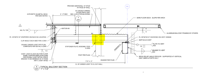 almost nothing stacked from floor to floor. The detailing quickly proved to be a complicated puzzle as well. almost nothing stacked from floor to floor. The detailing quickly proved to be a complicated puzzle as well.
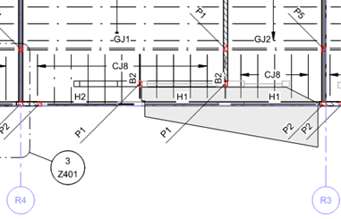
After several iterations, it was determined that the original concept of cantilevering out the balconies was not going to work without some additional interior girders and carry beams. The plans only provided a few specific locations where posts could be 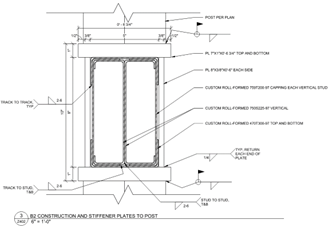 added to support the framing and stack all the way up the building. The residential wall layouts only overlapped at some specific locations. Once these points were located, the rest had to fall into place. The framing had to be turned in more than one direction to make everything work out. Figure 2 shows the typical framing layout with a grayed-in section for the balcony that had to be supported. added to support the framing and stack all the way up the building. The residential wall layouts only overlapped at some specific locations. Once these points were located, the rest had to fall into place. The framing had to be turned in more than one direction to make everything work out. Figure 2 shows the typical framing layout with a grayed-in section for the balcony that had to be supported.
Another wrench in the works was the brick cladding. The brick support had to be framed from the cantilevered elements along with everything else. This added one more part of the gravity loading that had to be carefully considered in the design of each element.
 To satisfy all of the often-competing design requirements, McClure utilized a cantilevered CFS member that could simultaneously support the balconies, brick, and exterior walls while fitting within the tight dimensional constraints of the floor/ceiling assembly. The resulting element was constructed using two studs and four tracks, all of which were custom roll-formed to produce a member with a cross-sectional profile of 8” tall by 4-7/8” wide. Figure 3 is the final detail used for all balconies on the project where “B2” represents the custom CFS beam. To satisfy all of the often-competing design requirements, McClure utilized a cantilevered CFS member that could simultaneously support the balconies, brick, and exterior walls while fitting within the tight dimensional constraints of the floor/ceiling assembly. The resulting element was constructed using two studs and four tracks, all of which were custom roll-formed to produce a member with a cross-sectional profile of 8” tall by 4-7/8” wide. Figure 3 is the final detail used for all balconies on the project where “B2” represents the custom CFS beam.
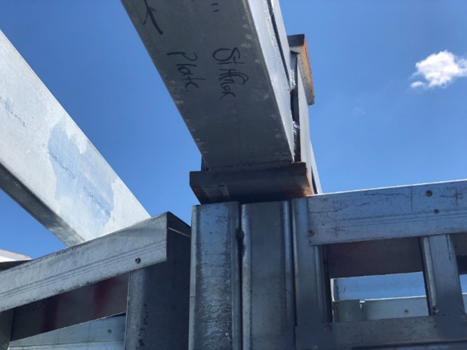
This B2 beam attached to girder joists on one end, cantilevered over the CFS posts, and supported the system of headers and brick relief at the exterior wall. Because it was made of CFS elements, web crippling was a significant design issue. To overcome this, the B2 beams run through the posts 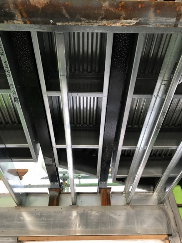 by means of a stiffener assembly to transfer the post load around the B2 beams. This special detail occurs where highlighted in Figure 3. The specific additional detail requirements are provided in Figure 4 and an as-built installation is shown in Figure 5. by means of a stiffener assembly to transfer the post load around the B2 beams. This special detail occurs where highlighted in Figure 3. The specific additional detail requirements are provided in Figure 4 and an as-built installation is shown in Figure 5.
To provide room for the aluminum balcony framing and drainage system, the B2 beams and C-joists (not shown in this detail) are dropped to be flush with the bottom of the joists. However, the floor deck still needed to be supported; therefore, 10” cross furring was added. These members are framed perpendicular to the dropped 8” framing and parallel to the typical floor joists which allowed the deck to be laid continuously without switching directions, shown in Figure 6. Because of the non-stacking and inconsistent load path, all of the balconies required full modeling. RISA 3D modeling design software was used to determine the flow of forces and design of the post and beam elements supporting the structure from floor to floor. Each balcony had to be carefully analyzed due to the uniqueness of each location around the building 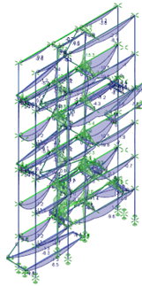 exterior. Figure 7 provides a snip from RISA 3D for a single controlling balcony stack. Forces were taken from the 3D model and used in calculations and analysis of the beam stiffener detail. exterior. Figure 7 provides a snip from RISA 3D for a single controlling balcony stack. Forces were taken from the 3D model and used in calculations and analysis of the beam stiffener detail.
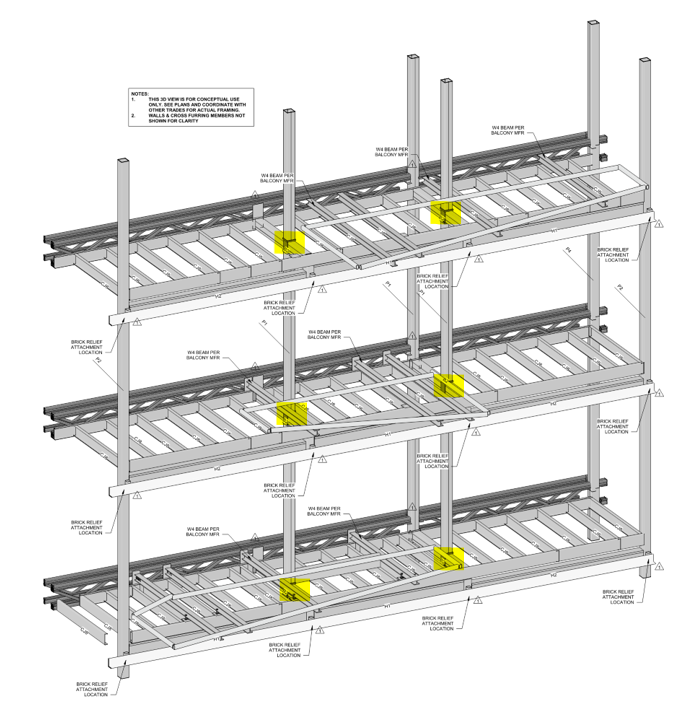
To get all elements properly detailed and shown on the contract documents, Revit was required to properly detail and locate each specific element of the balcony framing. Figure 8 shows a rendering from the Revit model for one specific balcony location. This was provided in the contract documents as a visual example for the typical balcony framing conditions. The beam stiffener plate detail can be seen highlighted in the rendering below.
|

